Baumer offers optimized, user-friendly 3D sensor CAD data that speeds up the engineering process and prevents errors during sensor installation and commissioning.
Three key advantages:
- CAD data is reduced to essential information, reducing the amount of data and loading time.
- The required data format is always available via the Cadenas platform, preventing compilation errors.
- Structure geometries extend the sensor CAD model, visualize the measurement principle and provide further important information for efficient mechanical engineering.
briefly
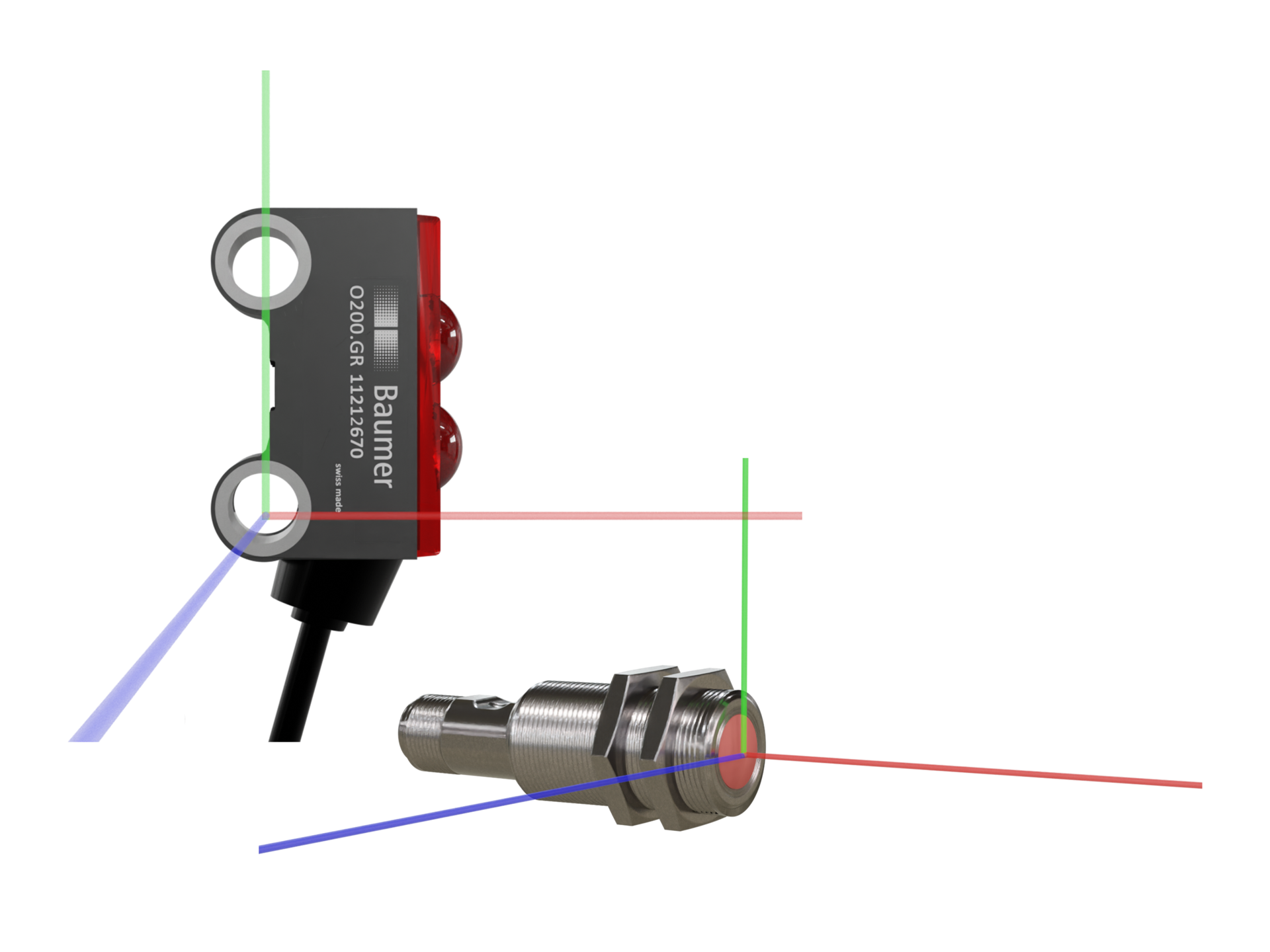
Mechanical data
Sensors form the basic structure of all sensor CAD models. The starting point of the coordinates is always in the same position according to the design of the sensors.
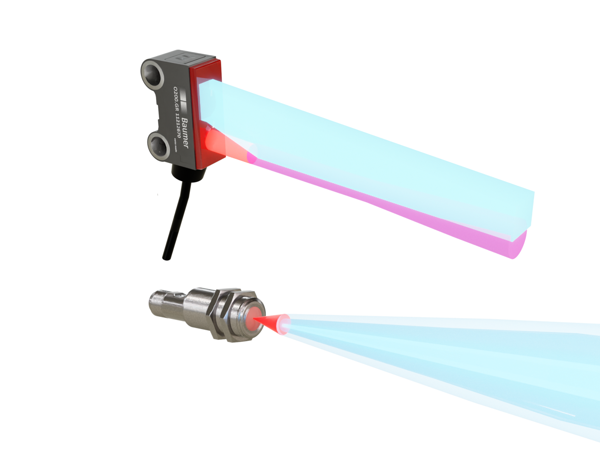
Building geometries
To significantly speed up engineering with sensors and avoid subsequent errors, Baumer's sensor CAD models are supplemented with structure geometry. These can be shown or hidden according to the user's needs.
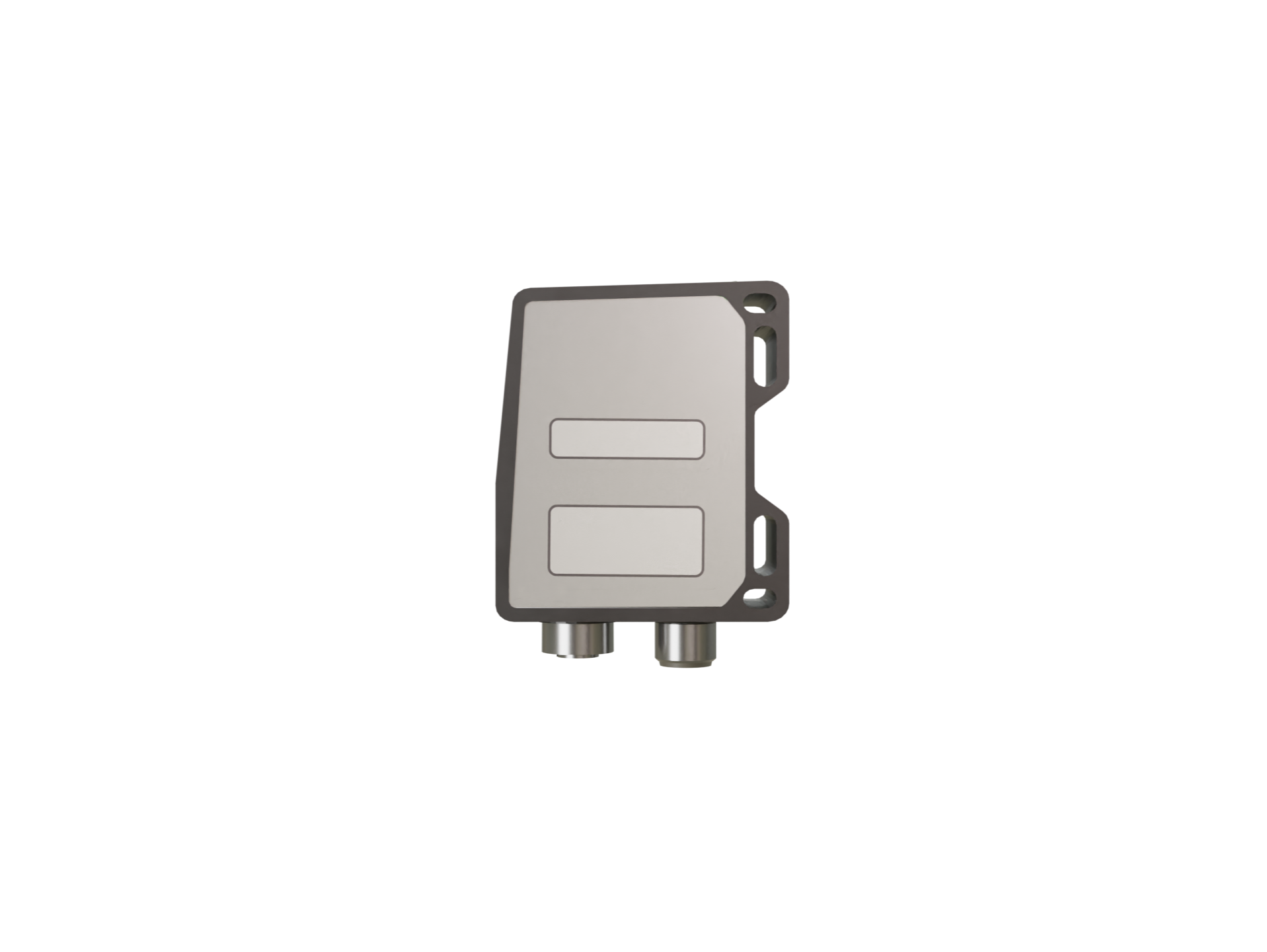
Labeling and notes
To ensure that sensors can be quickly identified even during installation, the sensor identification and warning notices (laser class) field is highlighted in color in the CAD model.
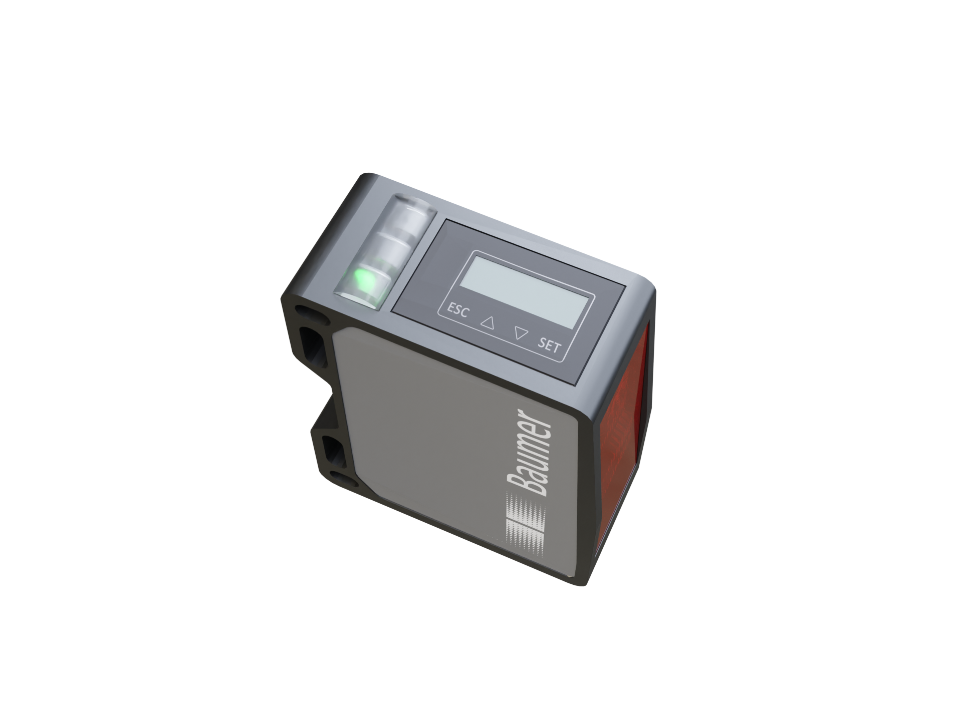
Display and operating elements
In order to be able to configure and read even in the installation state, the CAD model contains the location, size and representation of the display and operating elements.
optical sensors
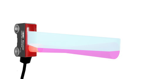
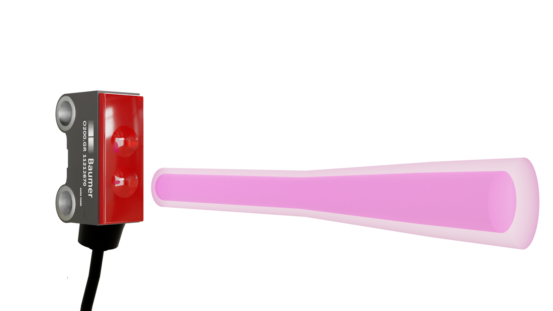
The beam path of optical sensors is represented by structure geometries in the CAD data. Therefore, the ray path no longer has to be created manually. This will reduce the potential for errors and engineering time.
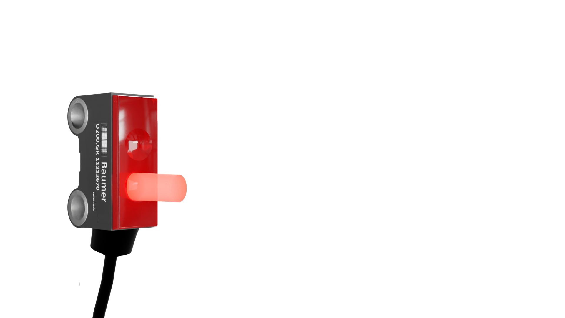
blind area
Object detection is not possible in this area.
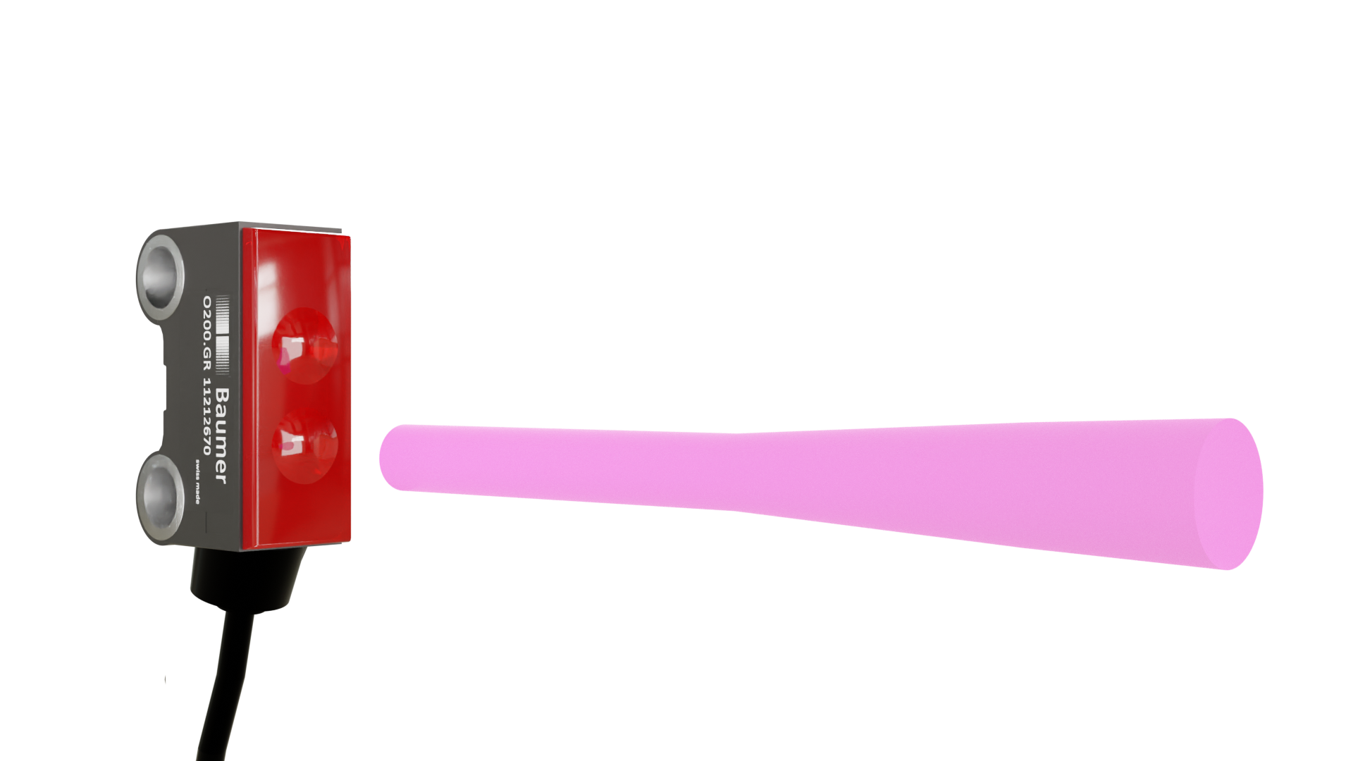
Detection/measurement range
Marking how light behaves and propagates. In this area, objects can be detected and distance can be measured.
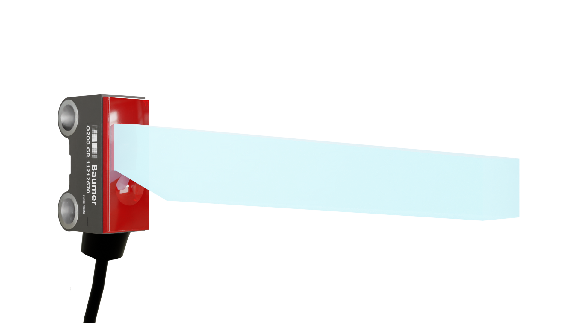
recipient area
This area should not be blocked by other parts, because the light from the object or reflector to be detected in this area will be reflected back to the sensor.
tolerance
Knowing the guaranteed tolerance range helps make the measurement more accurate. Baumer stands out by controlling the alignment of the optical axis, thus ensuring maximum planning reliability throughout the series.
ultrasonic sensors
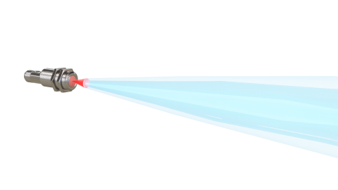
For ultrasonic sensors, the sound lobe is represented by structure geometries in the CAD data. This means that the vocal lobe no longer has to be created manually. This will reduce the potential for errors and engineering time.
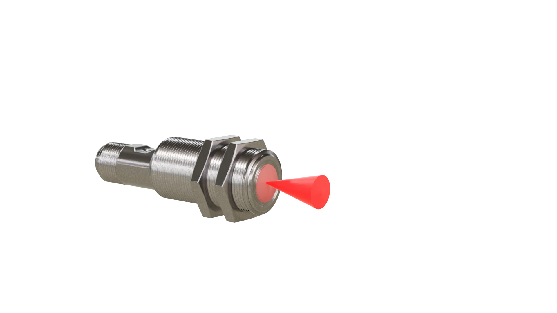
blind area
Object detection is not possible in this area.
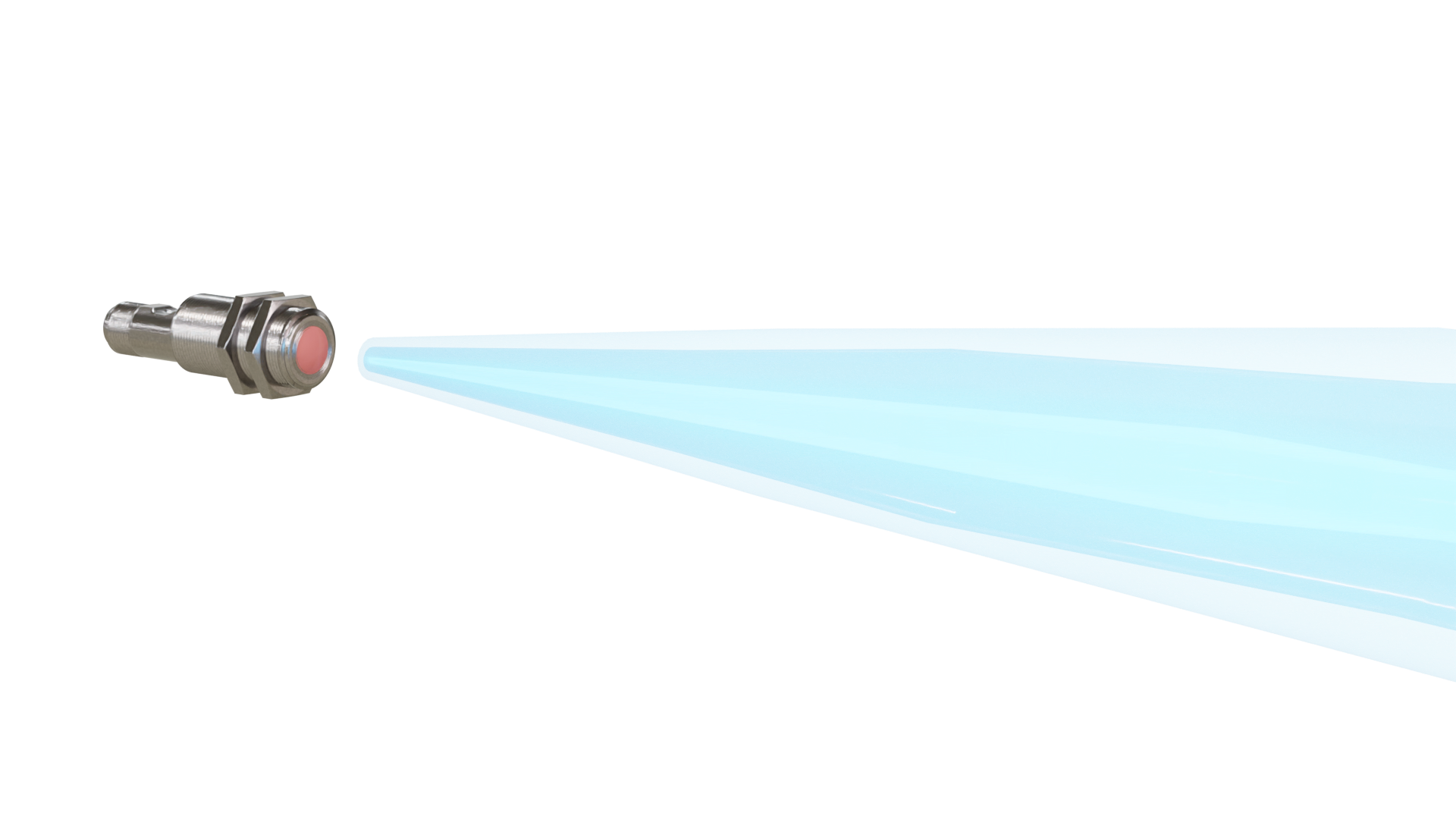
vocal lobe
Marking how the sensor's sound behaves. The sound curve for the standard object (30x30 mm) is shown by default. Object detection/distance measurement is possible in this area. With Baumer ultrasonic sensors with IO-Link interface, the sound lobe can be set to narrow, medium or wide depending on the application.
connection technology
Regardless of sensor technology, all sensors require a communication and power connection. Below are the three different variants offered by Baumer.
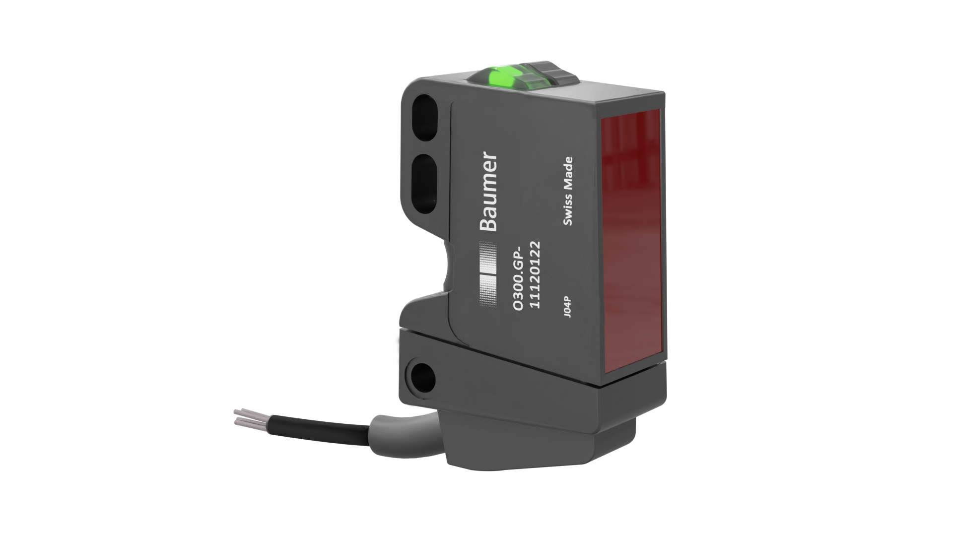
cable
The bend radius at the cable exit and the open cable end are visualized.
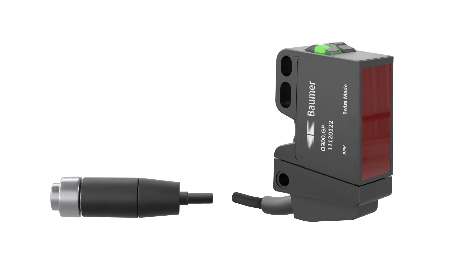
interconnect connector
In addition to the bend radius at the cable exit, the connector size is also displayed.
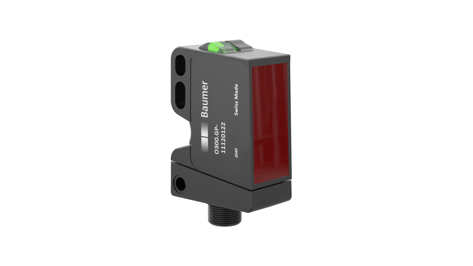
connector
The connector terminal is part of the sensor and therefore not the structure geometry.