How does the pressure sensor work?
The pressure sensor is essential for accurate pressure measurement. Baumer pressure sensors are based on resistive and piezoresistive pressure measurement. Changes in electrical resistance are measured and converted into an electrical signal. It is based on a metal, ceramic or piezoresistive material whose electrical resistance varies depending on pressure.
Pressure measurement is one of the most important and widely used technologies for monitoring and controlling machines and systems in process technology. Baumer offers a comprehensive portfolio of pressure sensors for a wide range of applications.
Absolute, relative and differential pressure
Absolute:
- Pressure measurement relative to vacuum
- Sealed sensor without relative compensation
- Monitoring or control of physical processes based on absolute pressure, such as vapor pressure
Relative:
- Pressure measurement relative to atmospheric pressure
- Relative compensated sensor
- "On" sensor is affected by its surroundings
- Monitoring or control of physical processes according to environmental conditions
- For example, lower pressure: Vacuum process for workpiece holding
- For example, top pressure: Hydrostatic level measurement in ventilated tanks
United:
- Gauge or differential pressure measurement measured from negative to positive
Differential:
- Measuring the difference between two pressures
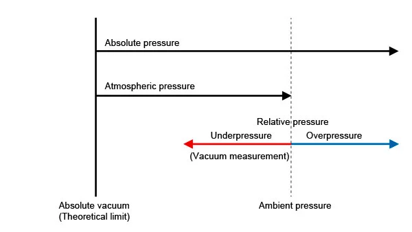
Baumer pressure sensors basically work with two different pressure measurement methods. The method is chosen according to the purpose for which the sensor will be used.
Resistive Pressure Measurement
Deformation of a thin metal or ceramic membrane leads to a change in electrical resistance. When pressure stretches the metal strip, the strip becomes longer and its resistance increases. When the strip is compressed, its cross-sectional area increases and its resistance decreases. This resistance change is recorded as an electrical signal and converted to pressure.
Piezoresistive Pressure Measurement:
This principle is also based on the change of electrical resistance with the deformation of the material, but it uses piezoresistive material. This material has the property that the mechanical stress occurring during deformation causes a change in electrical conductivity. The resistance change is larger than the resistive pressure measurement.
In addition, there are piezoelectric, capacitive and inductive pressure sensors, vacuum pressure sensors, frequency analog pressure sensors and Hall element pressure sensors.
Pressure Sensor Technology
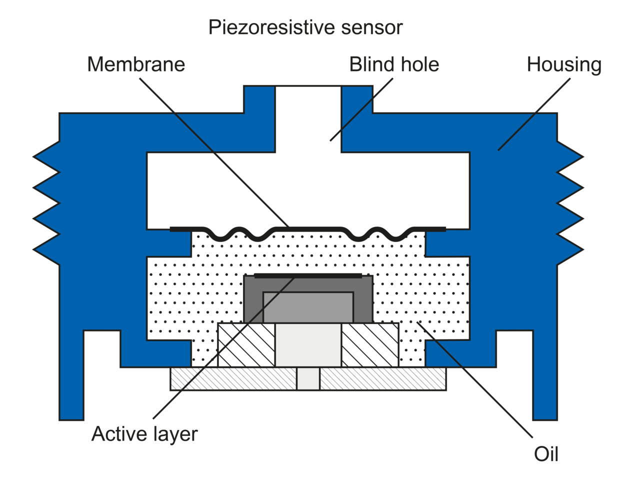
Semiconductor Silicon Sensor, Industrial Connection (piezoresistive pressure measurement)
In semiconductor materials, the change of specific resistance and hence the signal results from the variable mobility of electrons in the crystal structure. This mobility is affected by mechanical load. The sensitive silicon chip and process medium are separated by a stainless steel membrane (capsule). Depending on the application, paraffin or silicone oil is used for internal pressure transmission.
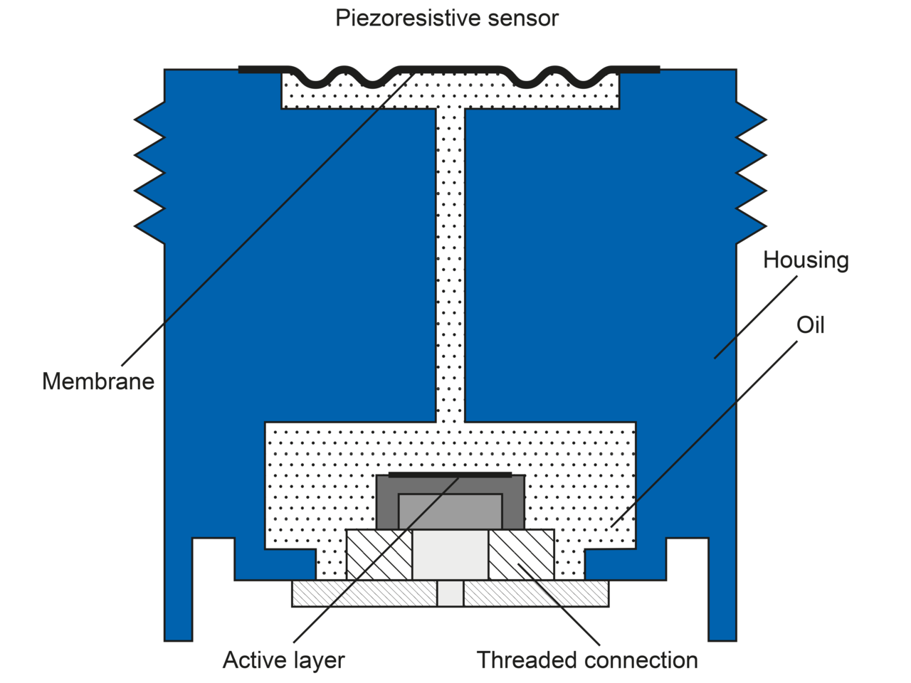
Flat Front Silicone Semiconductor Sensor (piezoresistive pressure measurement)
In semiconductor materials, the change of specific resistance and hence the signal results from the variable mobility of electrons in the crystal structure. This mobility is affected by mechanical load. The sensitive silicon chip and process medium are separated by a stainless steel membrane (capsule). Depending on the application, paraffin or silicone oil is used for internal pressure transmission.
Transmitters with piezoresistive silicon technology stand out with their high measurement accuracy and long-term stability. Thanks to their fully welded housing, they are durable and can be used in potentially explosive areas (ATEX). They are particularly suitable for small measuring ranges, such as hydrostatic level measurements from a height of 0.5 m.
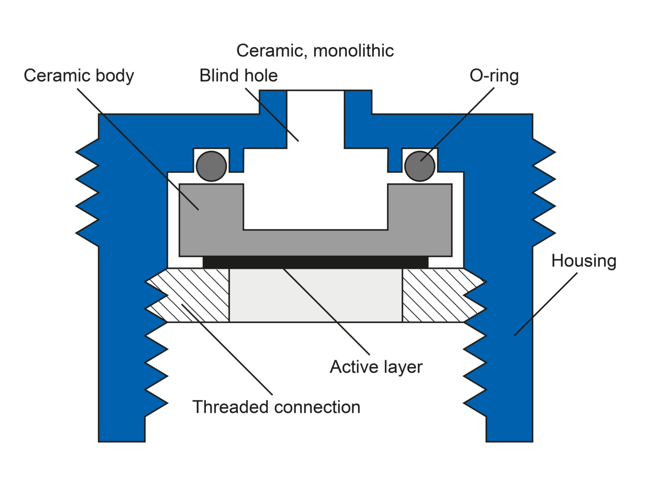
Ceramic thick film sensor, monolith (resistive pressure measurement), e.g. CTX/CTL
The basic body is a ceramic monolith with resistors printed on its back surface. Ambient air pressure acts on this surface as reference pressure. Therefore, essentially only relative pressure measurement is possible. Ceramic measuring cells are characterized by good long-term stability and corrosion resistance. Because ceramics cannot be welded to the process connection, sealing is required for media separation. In ceramic thick film technology, four resistors are combined to form a Wheatstone bridge. When pressure is applied, it is subjected to the greatest stress in the middle of the diaphragm and the greatest compression in the edge regions. In ceramic cells, the measuring membrane also serves as the membrane separating it from the medium. No internal transmission fluid required.
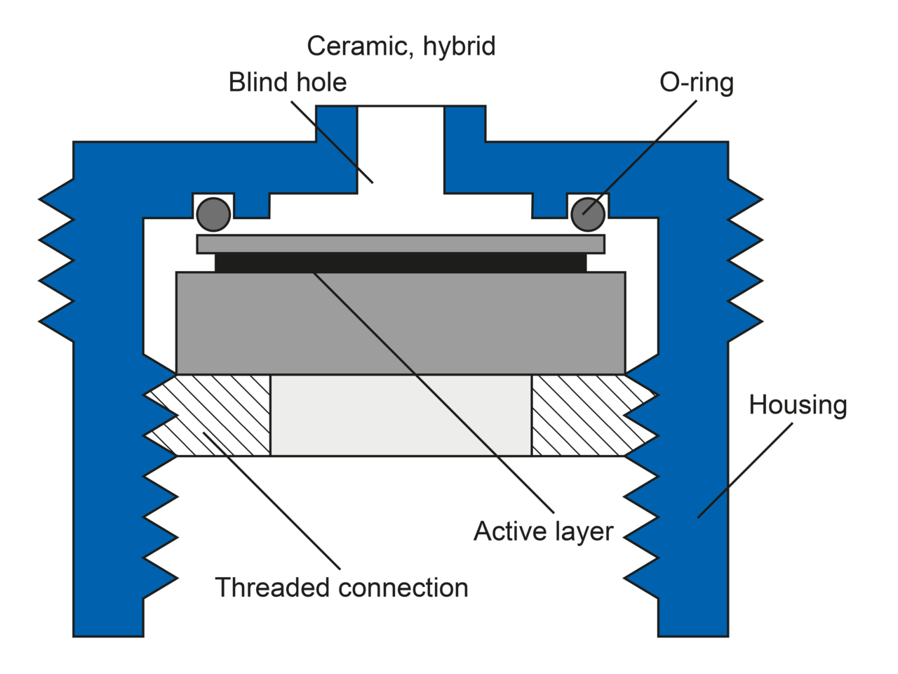
Ceramic thick film sensor (resistive pressure measurement), e.g. PBSN
The measurement film is between a thin ceramic membrane disk and a ceramic base body. The space required for bending the membrane is provided by a specially created gap. This volume can be ventilated or vacuumed with ambient pressure, allowing relative or absolute pressure measurement. Ceramic measuring cells are characterized by good long-term stability and corrosion resistance. Because ceramics cannot be welded to the process connection, sealing is required for media separation. In ceramic thick film technology, four resistors are combined to form a Wheatstone bridge. In thin film cells, the measurement membrane also serves as the membrane separating it from the medium. No internal transmission fluid required.
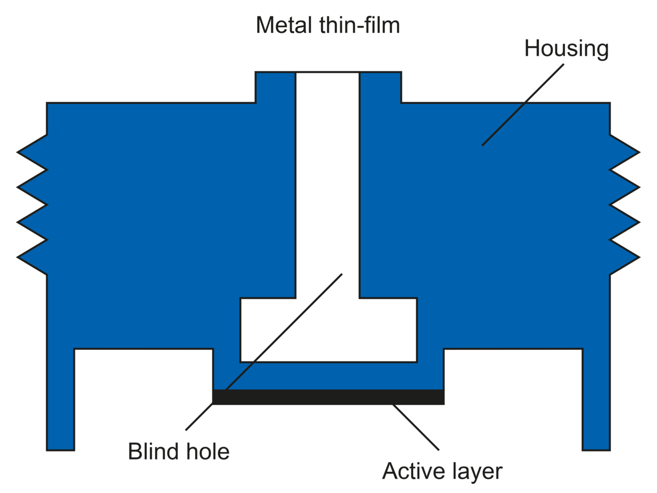
Metal thin film sensor (resistive pressure measurement)
The basic body is made of stainless steel. The resist structure is produced by photolithography. Thin-film measuring cells are distinguished by their excellent resistance to pressure peaks and burst pressure. In metal thin film technology, four resistors are combined to form a Wheatstone bridge. When pressure is applied, the resistors are subjected to the highest stress in the center of the membrane and the strongest compression in the edge region. In thin film cells, the measurement membrane also serves as the separation membrane from the medium. No internal transmission fluid required. It is generally used for relative pressure measurement because creating a vacuum behind the membrane is inherently challenging.
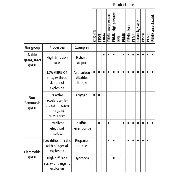
Suitability for gas applications
Pressure in sterilization processes
Hot steam is used to sterilize devices and equipment. Small elements, for example sensors (PBMH autoclavable), can be sterilized in a suitable chamber (autoclave). In larger systems, "Sterilization in Place" (SIP) is performed by passing hot steam through the system. Therefore, a sensor must be designed to be durable, but signal transmission is often not carried out during the sterilization process. The sensor must be able to withstand the current temperature and pressure for the relevant period (e.g. 30 minutes above 3 bar at 134 °C). Physically, pressure and temperature are directly related to each other and this is shown in the saturated steam curve.
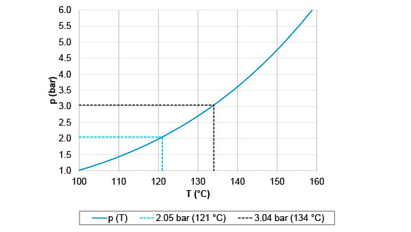
Baumer PBMx and PFMx pressure sensors are ideal for controlling the sterilization process. These sensors provide accurate values even with rapid changes in temperature and thus reliably control the process by monitoring the pressure. This ensures that the relevant temperature is reached.
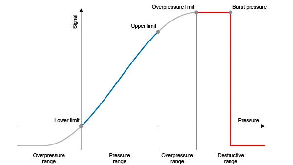
Explanation of terminology and relationships
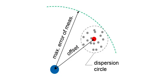
- Sensitivity:This describes the deviation of a single measurement from the average of many measurements and can be interpreted as a spreading circle. High sensitivity: small spreading circle, low sensitivity: large spreading circle.
- Accuracy:This defines the distance (offset) of the average value of many measurements from the true value. High accuracy: small offset, low accuracy: large offset.
- Standard error of measurement:This information is obtained by the straight line of best fit (BFSL) and defines the sensitivity (circle of spread).
- Maximum measurement error:This includes the standard error of the measurement and the offset of a sensor.
temperature dependence
The application may deviate from the reference temperature (e.g. 20 °C), so the standard or maximum measurement error must be treated differently.
- The "Reference Temperature Coefficient" (TC zero point) defines the temperature dependence of the zero point and hence its impact on accuracy.
- The "Measuring Range Temperature Coefficient" (TC range) defines the temperature dependence of the measuring range and hence its impact on accuracy, i.e. the standard measurement error.
- The TC zero point and the TC range together define the temperature dependence of the maximum measurement error.
Temperature dependence of maximum measurement error
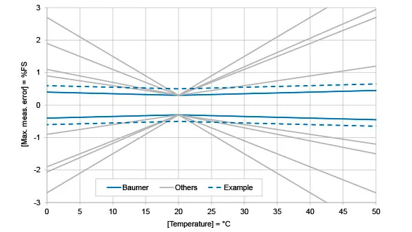
In most cases, if the operating temperature deviates from the reference temperature (e.g. 20 °C), a sensor with lower initial accuracy but more temperature tolerance should be preferred over a sensor with higher initial accuracy but less stability.
Error Indicator
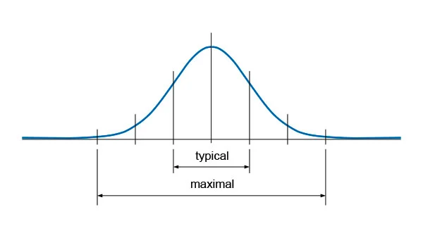
Baumer specifies “maximum error indication,” meaning that statistically, 99.7% of sensors comply with the specification. Some competitors specify a “typical failure indicator”, where 32% of products do not meet specification.
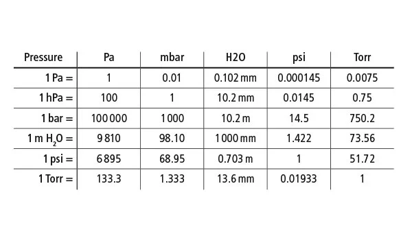
Unit Conversions