Functionality and Technology of Electromagnetic Flow Meters
Volumetric measurement based on the induction principle
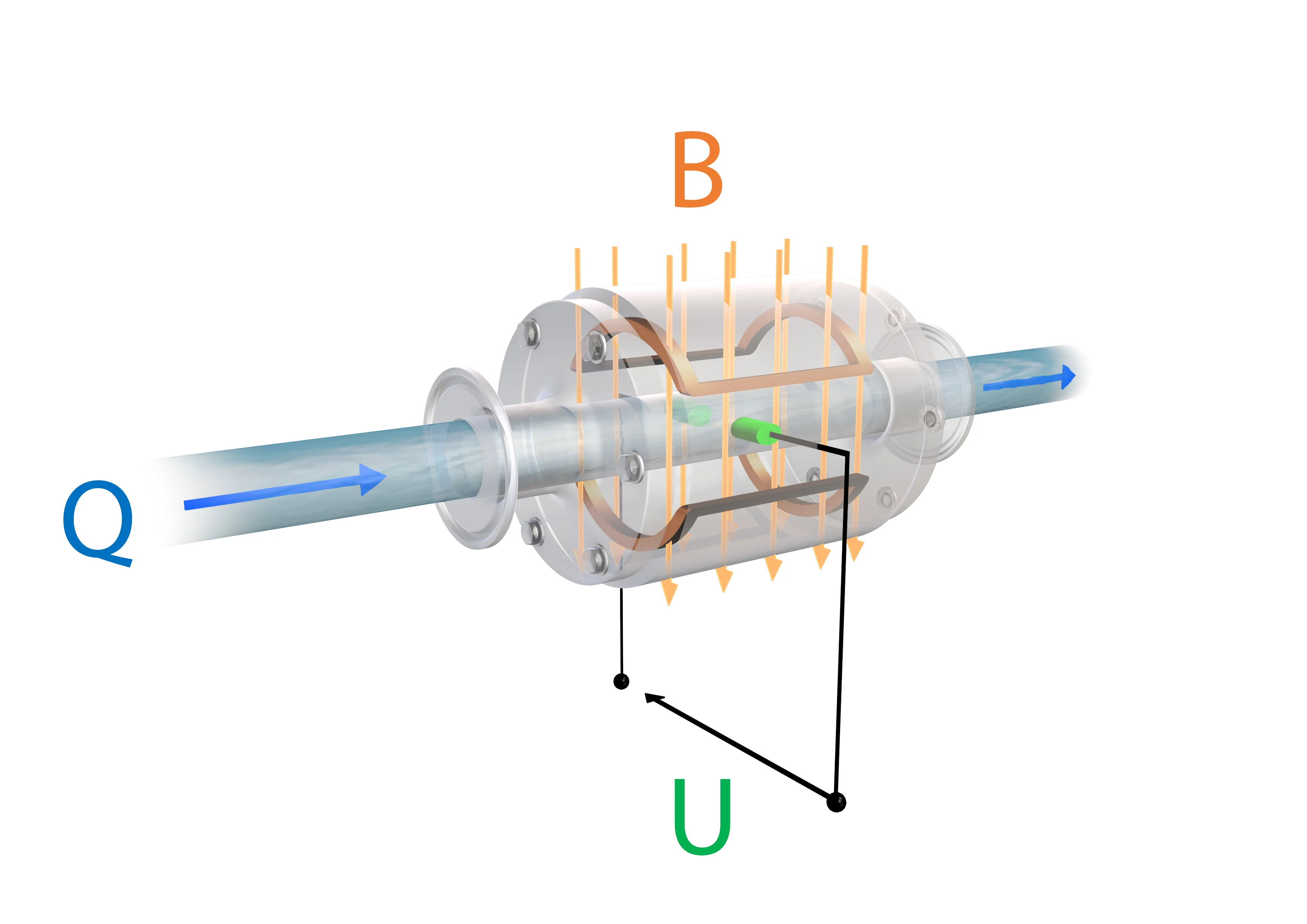
The measuring principle of the electromagnetic flow sensor is based on Faraday's law of electromagnetic induction. Air coils integrated in the measuring pipes create a permanent magnetic field (B) perpendicular to the direction of flow. The charge carriers of a conductive liquid (Q) deflect as they pass through the magnetic field, creating an electric voltage (U). The voltage is proportional to the average flow rate and is detected by the two electrodes. As the flow rate increases, the induced voltage also increases. This voltage signal is converted into a flow volume according to the nominal width of the pipe.
Construction of Baumer's electromagnetic flowmeters
Baumer's electromagnetic flowmeters consist of a transducer (PF75H/S with optional display) and a sensor. The sensor is installed directly in the process, that is, the pipe (inline), and measures the induced voltage created by the conductive medium as it flows through the measuring pipe. The sensor is available for different pipe sizes and applications.
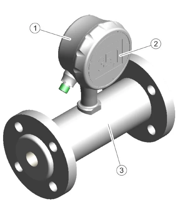
1) Converter
2) Optional display
3) Sensor
Views
Key parameters and menu functions can be displayed and configured in the CombiView display of the flow sensor.
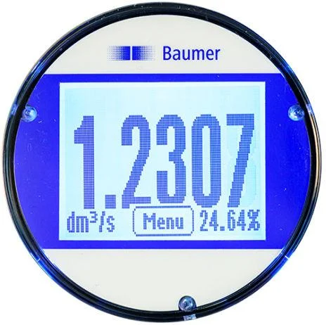
How is the screen configured?
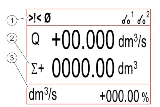
The screen is divided into 3 parts:
1. Status bar
Shows icons for alarm and error messages and the status of DFON relays.
2.Main part:
Depending on the selected display layout, the following measured values are shown:
- flow rate
- Positive partial counter
- Negative partial counter
- Net partial meter
- Positive total counter
- Negative total counter
- Net total counter
3.Extra stick:
Depending on the selected display layout, the following measured values are shown:
- Label or number tag
- Units of measured values
- Graphical representation of flow rate
For more information about the on-screen menu and available screen layouts, see the user manual for the PF75H/S sensor variants.
Wide range of Measuring Tube Coating Options
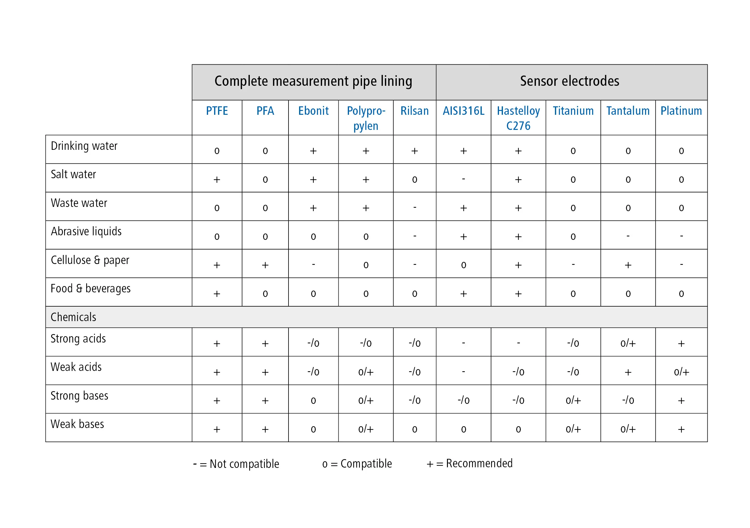
Electromagnetic flow sensors from Baumer offer a wide range of measuring tube coatings for every environment. The correct selection of the optimum material depends on the environment, solids rate in the environment, process pressure and process temperature.
Recommended Materials Table:
Choosing the appropriate flow meter
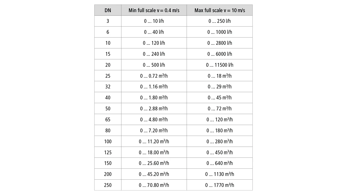
The selection of the appropriate flow meter depends not only on the measuring pipe coating but also on the nominal width of the measuring pipe, i.e. the sensor. The nominal width is usually determined by the existing pipeline. With the help of the alignment table below, you can make a control calculation based on the dominant flow rate of the system.
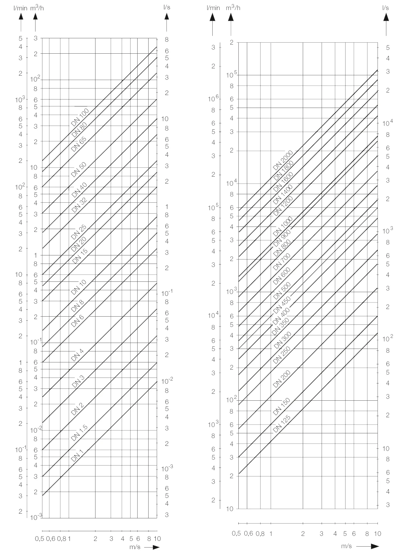
Deviation values
If there are deviations between the calculated nominal width of the flow sensor and the specified pipe diameter, the value of the sensor is usually lower. If the taper angle is less than 8°, it can be adjusted with tapered flange adapter parts. It is important to consider the pressure loss in the system. The pressure drop at the intersection of the diameter ratio d/D and the flow rate in the y-axis can be found in the overview below.
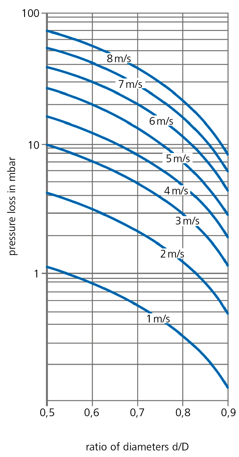
Rated flow: