Functionality and Technology of Strain Sensors
What is Strain?
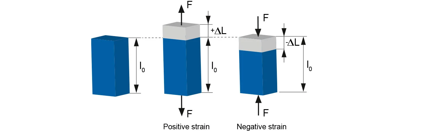
Strain is the relative change in length of a component or structure under tension. This may be an extension (stress) or contraction (compression). Strain can result from forces or moments applied to a structure (mechanical strain) and from thermal expansion in the case of temperature changes. Indirect force measurement via strain sensors determines mechanical strain.
How to Calculate Strain?
The relative length change is defined as the strain ε in [m/m] and is defined as the ratio of the absolute length change Δl to the total length l0. Strain is a dimensionless quantity. Its unit is ɛ. Small strains are expressed in [µm/m] (1 µm = 10^-6 m). In Europe it is usually used as [µm/m], and in Anglo-American countries as microstrain or microepsilon [µɛ]. When a component is extended it is called positive strain and when it is compressed it is called negative strain.
Why is strain measured?
In most cases, strain is measured to determine how much a material has been eroded by mechanical stress and therefore how much it has been stretched. At the same time, strain measurement provides information about the force that causes strain. This is a smart alternative for determining large forces. In a laboratory setting, strain gauges are typically bonded to a component. However, in mass production, it is easier to use screw strain sensors to create stable and high-quality conditions for indirect force measurement.
How Does Force Measurement with Strain Sensors Work?
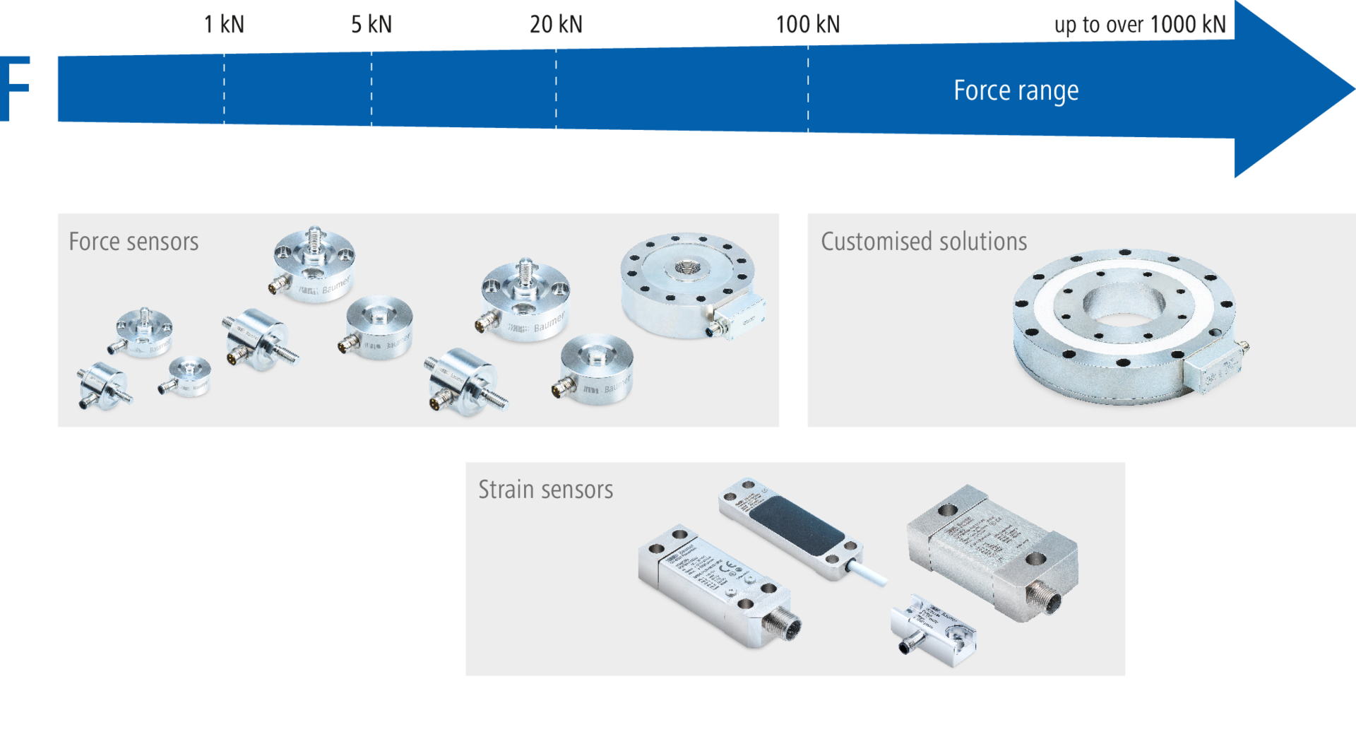
For large force ranges and rigid structures, strain sensors are a suitable alternative to force sensors. Unlike force sensors, strain sensors are not placed directly in the force flow but are instead screwed into the surface of the component of interest. Tension in the machine structure causes deformation. By measuring surface strain, strain sensors can easily determine the effective force. Indirect force measurement can cost-effectively determine large forces using a small strain sensor.
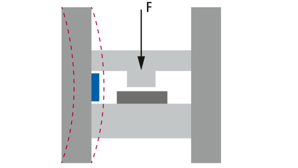
Indirect Force Measurement with Strain Sensors
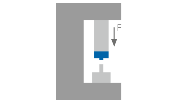
Direct Force Measurement with Force Sensors
In addition to strain sensors that can be screwed to the outside, versions that determine strain through a hole are also available. This may be useful depending on the system design.
Force Measurement – Should You Use a Strain Sensor or a Force Sensor?
How does strain lead to force?
Each component subjected to a force (F) experiences a certain strain (ε). In the linear elastic region, this strain always depends on the E-modulus (E) of the material, the cross-sectional area (A) of the material and the force. Using these three parameters, strain can be calculated as follows:
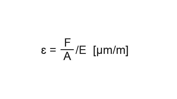
Using the equation
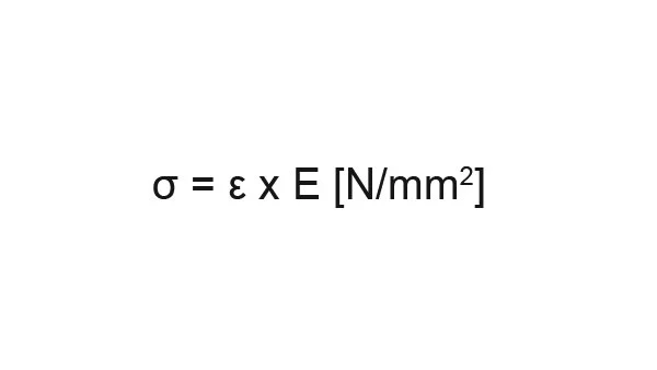
With this equation, it is also easy to extract the relevant component voltage. These calculations are based on Hooke's Law. In its simplest form, Hooke's Law determines the direct proportionality between strain (ε) [m/m] and stress (σ) [N/mm2] based on a material's modulus of elasticity (E) [N/mm2]. The mechanical design and material selection of the component are based on the resulting mechanical stress. For low strength steel materials a lower stress and therefore strain is acceptable. Higher stress and strain are allowed for high strength steel materials. Strain sensors have different measurement ranges that cover expected strains.
E-module
The strain experienced by a component always depends on the material of the component as well as the geometry and force. The determining parameter here is the E-modulus (modulus of elasticity). This describes the proportional relationship between stress and strain during the deformation of a solid body in a linear elastic field. The harder a material is, the higher its E-modulus. The E-modulus for tempered steel commonly used for strain sensors is E = 210,000 N/mm2. The E-modulus of aluminum is approximately 70,000 N/mm2; The E-modulus of hard rubber is 5 N/mm2.
Example calculation: strain to force

Strain on measured strain sensor: 240 µm/m
Steel bar width 20 mm x 20 mm -> Cross-sectional area A = 20 mm x 20 mm = 400 mm2
F= 400 mm2 x 210,000 N/mm2 x 240 x 10^-6 m/m = 20,160 N
How does a strain sensor work?

In strain gauge-based strain sensors, the mechanical parameter of force is converted into an electrical signal in four steps. The origin is a component that deforms when force is applied. This deformation is transferred to the strain sensor via a frictional joint. The strain sensor has a spring bellows made of tempered steel, which creates strain on the material surface due to external load. This strain is measured by strain gauges applied to the surface of the spring bellows. Strain gauges convert mechanical strain into electrical resistance change and function as mechanical-electrical transducers. As a result of this change in resistance, they produce a voltage change proportional to the strain. Thanks to the clever connection of the individual strain gauges with the Wheatstone bridge, even the smallest strains can be measured.
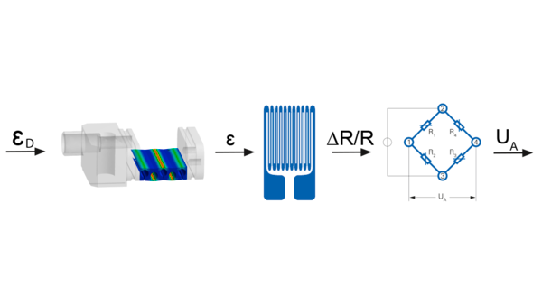
How does a strain gauge mechanical-electrical converter work?
Strain gauges are at the core of Baumer force and strain sensors and are used to detect strain on material surfaces. They usually consist of a support film (polyimide), a zigzag-shaped measuring mesh made of stabilizer and a coating layer. Strain gauges convert mechanical strain into electrical resistance change and function as mechanical-electrical transducers. The resistance change of strain gauges occurs proportionally and is defined as the k factor.
Design
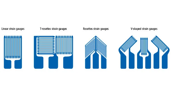
Metal strain gauges are available in different designs. Besides typical linear strain gauges, there are other typical designs such as T rosette strain gauges, rosette strain gauges, and shear strain gauges.
What is a Wheatstone bridge circuit?
Wheatstone bridge circuit is a special electrical resistance circuit that helps measure electrical resistance changes precisely. In the full bridge circuit used in sensor construction, four strain gauges are always connected together in a specific pattern. The bridge circuit consists of two voltage dividers connected in parallel and is fed by a common power supply, the bridge power supply UB.
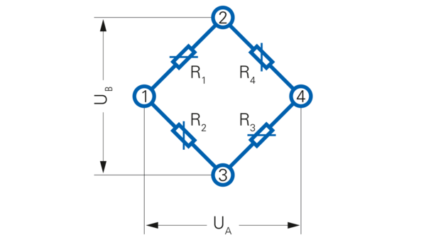
Thanks to the Wheatstone bridge circuit, even the smallest resistance changes can be detected precisely. Changes in individual resistances lead to bridge unbalance UA, which can be easily measured. The measurement signal of the bridge behaves proportionally and is proportional to the supply voltage. The typical measurement signal of strain gauge sensors is in the range of 0.4 to 3.0 mV/V.
Are strain sensors fatigue resistant?
Baumer strain sensors are mechanically fatigue-resistant for at least 10 million cycles over the entire strain range (e.g. +/- 500 µm/m). In this way, processes with high cycle and load numbers can be monitored in positive and negative directions.