Functionality and Technology of Conductivity Sensors
Baumer conductivity transmitters are designed for media separation and analysis in the food and beverage industry and water treatment applications. These transmitters provide outstanding benefits in terms of accuracy and imaging options.
Working Principle of Baumer AFI Inductive Conductivity Sensor
Distinction between conductive and inductive technologies
Setups of classical conductivity sensors with electrodes in galvanic contact with the medium are limited to the point where high ion concentrations can cause a polarization effect. This may create additional resistance, which may distort the measurement result. Similarly, precipitates (e.g., sodium hydroxide) can form insulating layers that can make conductivity measurement impossible.
In applications with high ion concentrations, such as leachings and acids with conductivity values in the range of 100 mS/cm, and when there is a risk of precipitation, inductive technology is the only reliable option that provides reliable conductivity measurement and therefore reliable process control. However, the inductive measuring principle is not suitable for measuring very small conductivity values. The smallest measurement range is 500 µS/cm (0.5 mS/cm), and measurements can be made with a sensitivity of approximately 50 µS/cm in this range.
Design of the inductive conductivity sensor AFI
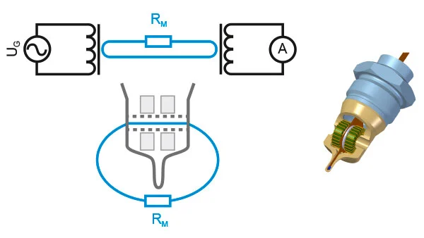
The sensor element contains two ring-core coils in a seamless PEEK housing, which act as two virtual transformers arranged in series. The first primary winding is fed by an oscillator in the kilohertz range. The current measurement gate forms the liquid loop, which can be considered as the common winding of two transformers. The secondary winding of the second transformer is connected to a galvanometer. The volume of the fluid resistance RM creates an associated current measurement value, which, together with the known oscillator voltage UG, is converted into the conductivity value GM.
The sensitivity of the galvanometer must be adjusted for different ranges of conductivity values. By activating the control inputs, the user can set freely defined measuring ranges that can be selected during operation.
The inductive measuring principle does not depend on fluid movement in the current measuring passage. However, it is recommended to align the channel in the flow direction to achieve better cleaning results. The symmetrical design of the channel accommodates both flow directions without the risk of clogging by media components.
There is a sensitive and highly responsive Pt100 temperature sensor integrated into the tip of the sensor element. The ambient temperature measured by this sensor is available as a measurement signal and is used for physical temperature compensation of the raw conductivity value.
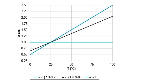
Temperature Compensation
The conductivity of a liquid generally depends on temperature. For most aqueous solutions, this increase is +2%/K. To be able to compare measurements, the meters directly return the determined conductivity to a reference temperature. This is usually defined as 25 °C. In addition to this definition, the AFI also provides a temperature coefficient entry in %/K. If you wish to dispense with temperature compensation, this should be set to 0%/K. Nonlinear temperature coefficients can be specified with an additional square element.