Functionality and Technology of Inductive Sensors
Baumer inductive proximity switches are electronic sensors that do not require contact. Inductive sensors recognize conductive metal targets.
The oscillator creates a high-frequency electromagnetic field that radiates from the sensing surface of the switch. When a conductive metal object enters this electromagnetic field, eddy currents are induced in the metal and a change in the amplitude of the oscillations occurs. As a result, a voltage change occurs at the output of the oscillator, which changes the state of the trigger and changes the output state.
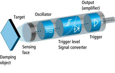
Detection Characteristics of inductive proximity switches
Detection Distance
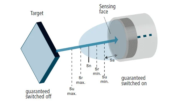
International standard EN 60947-5-2 defines the detection distance as follows: The detection distance is the distance at which a standard target moving towards the detection surface of a proximity switch causes a signal change.
Standard Target
The standard target is defined as a 1 mm thick square plate made of Fe 360 (mild steel). The edge length is the greater of the sensing surface diameter or three times the nominal sensing distance (Sn).
Nominal Sensing Distance (Sec)
The nominal sensing distance is a classification parameter determined without taking into account processing tolerances or variations due to external conditions such as voltage or temperature.
Effective Sensing Distance (Sr)
It is the effective sensing distance of a proximity switch measured under specific temperature, voltage and installation conditions. For inductive proximity switches, it should be between 90% and 110% of the nominal sensing distance at 23 ±5 °C.
Usable Sensing Distance (Water)
Sensing distance measured across the temperature range of a proximity switch and at supply voltage at 90% and 110% of nominal value. For inductive proximity switches, it should be between 90% and 110% of the effective sensing distance.
Safe Sensing Distance (Sa)
It is the distance from the sensing surface at which the proximity switch operates under defined conditions. For inductive proximity switches, the safe sensing distance must be between 0% and 81% of the nominal switching distance.
Particularly Large Sensing Distances – GammaProx
The sensing distances of the inductive GammaProx family are up to five times greater than the CENELEC standard value. This enables equally safe and reliable detection of steel and non-ferrous metals. Thanks to the increased sensing distance, it is often possible to choose greater distances to moving objects, which allows larger installation tolerances, prevents damage and increases plant reliability.
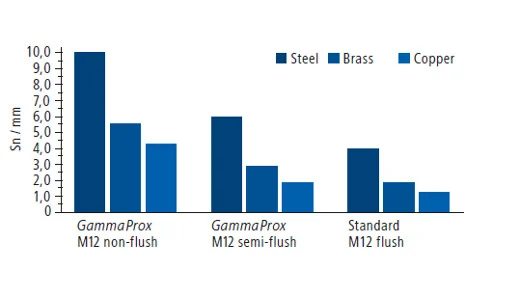
Due to the increased switching distance, GammaProx sensors respond more sensitively to the surrounding material. Therefore, mounting on the front surface is not possible in all materials. The exact installation conditions and correction factors are specified in the data sheets.
Correction Factor (Cf)
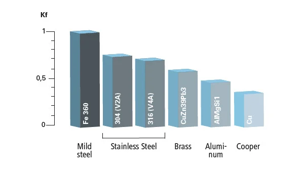
If metallic materials other than the standard measuring plate (Fe 360) are used, the specified switching distances must be multiplied by the material correction factor specified in the data sheet. These results should be considered as a guide. If correction factors are not specified in the data sheet, the standard values specified in this table can be used. Geometries different from the standard measuring plate also affect the switching distance.
When detecting non-metallic materials coated with aluminum foil or a thin layer of aluminum or copper, the detection distance achieved can be close to the value of mild steel. The actual Sn depends on the thickness of the layer and the alloy composition.
Factor 1
Standard sensors experience up to a 70% reduction in detection range towards non-magnetic metals. Factor 1 sensors have a microcontroller that compensates for this reduction. Therefore, factor 1 sensors do not have the disadvantage of material-dependent distance reduction. They are distinguished by low temperature drift and high switching speed, making them ideal for measurement of rotational speed on aluminium, non-ferrous metals and gear wheels or perforated disks.
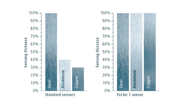
The uniform distance of the sensor offers exceptional flexibility in system design and sensor mounting. However, the benefits of Baumer sensors go even further: They are the fastest in their class in terms of detection range and have outstanding detection range.
hysteresis
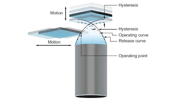
During approach and departure from the target, there is a difference between the operating and release point, defined as hysteresis. Hysteresis is built into the sensor's properties to prevent possible false detections due to vibration.
Switching Frequency
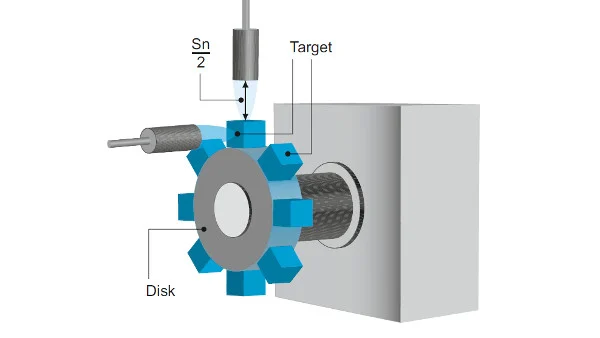
In accordance with EN 60947-5-2 standards, switching frequency is the highest possible number of switches per second.
resolution
Overall Resolution
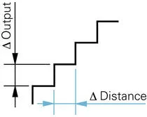
Resolution represents the smallest distance change that will produce a measurable signal change in the sensor output. Resolution may be affected by high frequency electrical interference (noise) or the resolution of digital/analog converters.
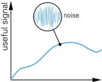
Dynamic Resolution
During very fast measurements (high scan rates) signal noise completely affects the signal processing. Filtration is possible to a limited extent without impact on the usable signal.
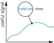
Static Resolution
Very slow object movements (low scan rates), such as temperature expansion of shafts, allow high-frequency interference to be filtered out. This technique significantly increases resolution compared to dynamic measurements.
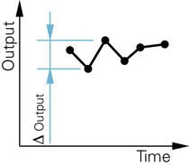
Repeat Accuracy
Repeat accuracy refers to the difference between measured values of consecutive measurements over a period of 8 hours at an ambient temperature of 23 °C ± 5 °C.
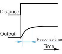
Response Time
The time required for a sensor's signal output to rise from 10% to 90% of its maximum signal level is called response time.
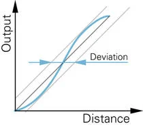
FS Linearity
Linearity describes the deviation between the output signal and a straight line. The final value of the measuring range (FS or Full Scale) is given as a percentage. For applications where the linearity shown is insufficient, the following alternatives are available:
- Polynomials for mathematical linearization of the sensor curve in the controller
- Sensors with linear output curves