How is force measured?
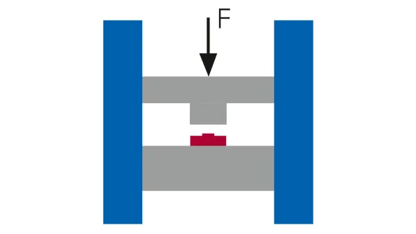
To measure force with force sensors, the force sensor must be positioned so that all force passes through the sensor and the sensor is directly in the force flow. It is important here to apply the force from the center and to have a sufficiently rigid contact surface.
How does the force sensor work?
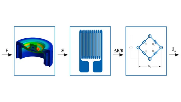
In strain gauge-based force sensors, the processing of the mechanical variable into the electrical signal takes place in three steps. The starting point of every force sensor with a strain gauge is a patterned metal foil on which external loads create tension on the surface of the material.
This stress is measured with strain gauges applied to the surface of the patterned metal foil. Strain gauges convert mechanical strain into a change in electrical resistance and act as mechanical-electrical converters. This resistance change creates a voltage change proportional to the force. By intelligently connecting individual strain gauges in the form of a Wheatstone bridge, even the smallest strains can be measured.
Key advantages of strain gauge-based force sensors are:
- Strain gauges as a proven and cost-effective technology for force sensors
- High level of accuracy and excellent linearity and hysteresis behavior
- Very good temperature compensation by connecting to Wheatstone bridge circuit
- Measurement of static and dynamic loads possible
- High fatigue strength and high vibration resistance of strain gauges by selecting suitable materials for the sensor body
- long term stability
Patterned metal foil - Mechanical converter
The starting point for any force sensor is a patterned metal foil that changes shape with the application of force. The advantage here is that the deformation is completely elastic. Deformation occurs within the limits of elasticity, so after applying the load, the patterned metal foil returns to its original shape under zero load.
Force sensor material
Baumer force sensors are generally made of high-strength stainless steel (1.4542). For special applications, force sensors made of tempered steel, aluminum or other metal alloys are also available.
Design and fatigue strength
The challenge in the design and layout of patterned metal foil lies in the conflict between limiting the softest possible structure and the material boundary for good measurement performance. With the help of complex computer-aided FEM simulations, the patterned metal foil is designed for the highest possible strain within its elasticity limits. The aim is to create as homogeneous a region as possible to which the strain gauge can be applied. The fatigue resistance of the force sensors is guaranteed by the subsequent strength evaluation according to the well-known FKM guideline. This means that Baumer force sensors can be dynamically loaded up to their rated force and used for more than 1 million load cycles in continuous operation.
Construction types
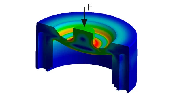
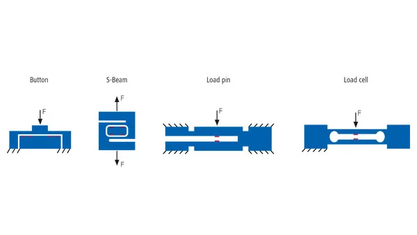
Baumer force sensors are usually designed with a diaphragm metal foil. An important advantage of this design is that they have very small dimensions and can be produced cost-effectively. Additionally, diaphragm force sensors can often seal very well hermetically and can therefore also be used in harsh environments. Other possible designs include S-shaped metal foils, cylindrical metal foils or bending beams.
Strain gauges - Mechanoelectric transducer
Strain gauges are the core element of Baumer force and strain sensors and are used to measure stresses on the material surface. They usually consist of a carrier film (polyamide), a zigzag-shaped measuring grid made of constantan material and a top layer. Strain gauges function as mechanical-electrical transducers by converting mechanical stress into a change in electrical resistance. The change in resistance of strain gauges is proportional and is called the K factor.
Design types
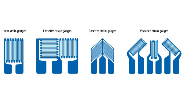
Metallic strain gauges for sensor construction are available in different designs. Besides typical linear strain gauges, other typical designs include T-rosette strain gauges, rosette strain gauges, and shear strain gauges.
Wheatstone bridge circuit
The Wheatstone bridge circuit is a special circuit arrangement that allows precise measurement of changes in electrical resistances. In the full bridge circuit used in sensor construction, four strain gauges are connected together in a specific order. The bridge circuit consists of two voltage dividers connected in parallel and supplied with bridge power UB from a common voltage source.
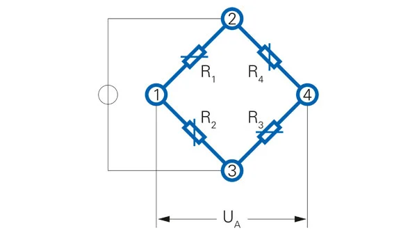
The smallest resistance changes can be detected precisely with the help of the Wheatstone bridge circuit. Changes in individual resistance values result in a bridge offset UA that can be easily measured. The measurement signal of the bridge is proportional and proportional to the supply voltage. The typical measurement signal of strain gauge force sensors is between 0.4 and 3.0 mV/V.
Temperature characteristics
Temperature changes during measurement are a challenge for strain gauge-based force sensors. A temperature change of 10 °C already produces an absolute length change of 0.012 mm in 100 millimeters of steel. Expansion induced by temperature changes can be fully compensated by selecting a suitable strain gauge with appropriate material expansion coefficient and cleverly connecting the strain gauges after the Wheatstone bridge circuit.
Bridge Amplifier - Electrical Converter
The bridge amplifier supplies the Wheatstone bridge with a stable supply voltage. The resulting signal of the bridge is amplified by the amplifier and displayed either analogue (voltage output/current output) or via digital interface (CAN/IO-Link). Baumer bridge amplifiers are currently available with a voltage output of ± 10 V DC and a current output of 4...20 mA.
With the help of bridge amplifiers, strain gauge-based force sensors can be easily zeroed during application, thus eliminating zero offsets during assembly. Another advantage of measurements with bridge amplifiers is the very good noise behavior even in highly dynamic applications.
Physical foundations of force measurement
What is force and how is it calculated?
The force F in newtons [N] is the product of the mass m of an object in kg and the gravitational acceleration g in m/s².
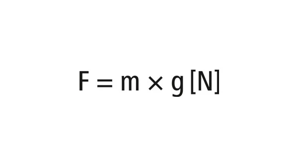
This results in a force of 1,000 N for a mass of 100 kg. In practice, a simple approximation of g = 10 m/s² is used for gravitational acceleration.
What is expansion and how is it calculated?
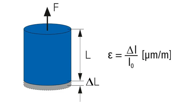
When a force is applied to an object, compression occurs in the case of pressure force and extension occurs in the case of tensile force. This relative change in length is defined as the expansion ε in units [µm/m], and the absolute length change Δl is defined as the ratio of the total length l0.
Modulus of Elasticity (MOE)
The actual elongation of a component is related not only to its geometry and force, but also to the material of the component. The determining characteristic value is the modulus of elasticity. This describes the proportional relationship between stress and expansion during deformation of a solid body in the linear elastic range. The following principle applies: the harder a material is, the higher its modulus of elasticity. The standard modulus of elasticity used in converter construction is E = 200'000 N/mm² for stainless steel and 70'000 N/mm² for aluminum.
From force to expansion
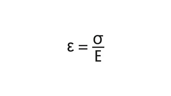
Each component subjected to a force F also experiences a certain expansion ε. This expansion always depends on the elastic modulus E of the material, the cross-section A of the material and the force. Using these three parameters, the expansion can be calculated as follows:
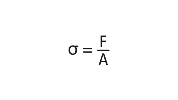
The relevant component voltage σ is calculated as follows:
K factor
The K factor of the strain gauge defines the sensitivity of the strain gauge. This expresses the linear relationship between the elongation of a material and the relative change in resistance.
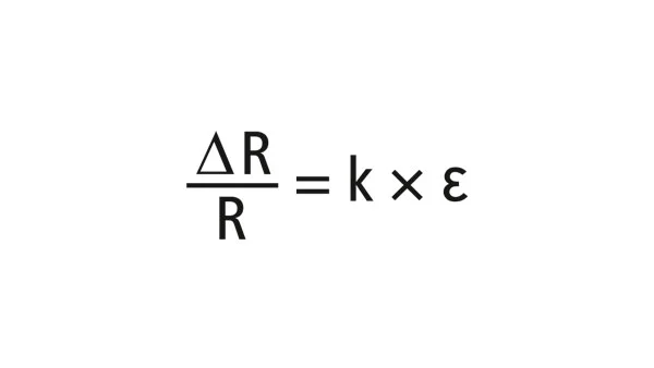
The K factor for a typical strain gauge is 2.05 for constantan grids.
Wheatstone bridge equation
With the help of the elongation and K factor, the expected measurement signal can finally be calculated using the Wheatstone bridge equation. In a typical flexural beam, the measurement signal is calculated as follows:
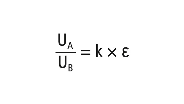
It should be noted that two tension meters respond to tension and two tension meters respond to compression. Ideally, the amount of expansion at all measuring points should be the same.
Distinction from weight measurement
Time and time again, project managers or development engineers are tasked with making weight measurements on construction machinery or the like. Physically, there are no specific differences between force sensors and load cells. The only difference between them is the calibration of the sensors. Unlike load cells, force sensors are always calibrated to a nominal force defined in N rather than a weight defined in kg. Baumer sensors are calibrated as force sensors and used for force measurement.
Standard force sensors
The characteristic values of force sensors are defined in the VDI 2638 directive. The definitions made in this guideline make it possible to create a common language basis for force sensors that allows comparison of technical data. Further information on individual characteristic values can also be found in our force measurement glossary.