Shading Correction (Flat Area Correction) with Baumer GAPI SDK [AN201803]
Baumer Cameras, Baumer GAPI SDK v2.9.2 and later
Baumer GAPI ghosting correction (flat field correction) helps you calibrate your imaging system to significantly reduce brightness differences caused by the camera/lens system or irregular light sources.
Login
In imaging systems, it is not uncommon for brightness changes to occur across the full image frame for a variety of reasons. These changes can negatively impact algorithms developed to perform various tasks of an imaging system, such as object detection or code reading.
“Flat area correction,” It is a technique used to improve quality in digital imaging. The goal is to eliminate artifacts in 2D images caused by variations in the detector's sensitivity from pixel to pixel and/or distortions in the optical path. This is a standard calibration procedure used on everything from pocket digital cameras to giant telescopes. Flat field correction refers to the process of compensation for different gains and dark currents in a detector. Once a detector is properly flat field corrected, a uniform signal produces a uniform output (hence flat field). This means that a signal based on the subsequently detected phenomenon exists and is not due to a systematic error.”
Wikipedia:https://en.wikipedia.org/wiki/Flat-field_correction [05.06.2018]
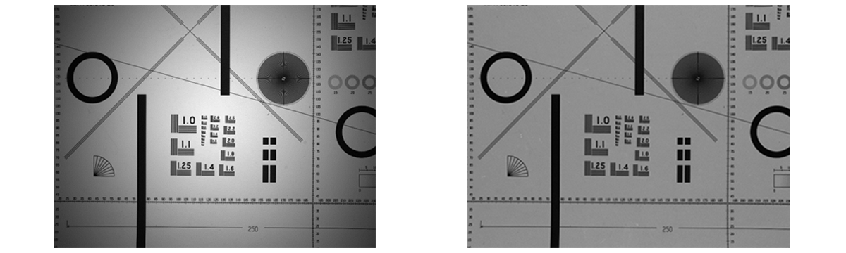
It is important to understand the limitations of the algorithm. If the brightness difference in an image is greater than 25% to 30%, then we can consider that there are problems with component selection and the algorithm may not produce the expected results. Therefore, you may need to consider replacing system components.
Step 1: Measuring the Imaging System
Note:
For best results, measurements should be made in the real environment of the entire imaging system setup. It is important to understand that only static effects can be reduced. This means you need to recalibrate the system if you change lenses, apertures or light sources.
Once you have set up the Imaging System and adjusted the aperture and light settings to your liking, the example will guide you to create 2 data sets for the darkest (dark field frame) and brightest image (light frame).
The example will take several images for each set and create an average to reduce the effect of sensor noise. These average images are then used by the imaging system to calculate the data required to correct the acquired images.
You need a clean, white target for luminous reference; Any artifacts (such as dirt or even the texture of the paper) may be visible after calibration! The target must cover the entire surface you want to calibrate. Ideally, it is recommended to use a calibrated target, but this is not absolutely necessary.
Imaging System Setup
- Set up your imaging system, including camera, lens and light sources, according to your planned use.
- Configure the exposure time, aperture, gain, and intensity of light sources required for your application.
- Set a constant exposure time to ensure the image is not oversaturated. This can be done with the help of Baumer Camera Explorer (Histogram View, F7). Also make sure the gain is set to the lowest level to minimize noise in the image.
Obtaining Dark Field Reference
This step is optional to ensure full flat area correction. If only shading correction is needed, you can skip this step. Measurement is only required once for a given camera.
- Compile and launch the 016_FlatField_Calculation.cpp sample in a convenient location.
- To create the dark field reference, it is necessary to completely block the light coming to the camera sensor. This is best done by closing the lens cap or removing the lens and attaching the protective cap that came with your camera.
- To get the Dark Area Frame, press “D” Press the key.
- The sample will take several images and save the calculated reference data as Baumer Raw Image (dark_field_reference.brw) in the folder where the sample is located. Brw files can be viewed with Baumer Camera Explorer.
- The sample will notify you when the measurements and calculations are successful. If the sample tells you problems, double-check your Imaging System setup and repeat the measurement.
Get Light Reference
- Now you need to adjust the system for the light frame. Please remove the lens cap or reattach the lens and turn on all configured light sources.
- If your system's illumination is shining towards the camera (for example, to capture the 2D shape of an object), remove any objects from the Imaging System's field of view. Otherwise, place a completely white sheet of paper where the object will be located. Make sure the entire field of view is covered by this paper!
- Restart the compiled example and use “L” to get the Light Frame. Press the key.
- The calculated reference data will be saved as Baumer Raw Image (light_reference.brw) in the folder where the sample is located.
- The sample will notify you when the measurements and calculations are successful. If the sample tells you problems, double-check your setup and repeat the measurement.
- Now everything is ready to fix the images received by your system.
note
If a non-ideal target (for example, paper) is used, artifacts or contaminants in the target may be visible in the corrected image. In this case, Baumer GAPI box and median filters can help reduce unwanted artifacts. However, these filters should only be used as a last resort as they can negatively impact shading correction.
An example of how to use filters:
                bo_uint r = m_pShading->GetFilter(BGAPI2::Ext::Sc::Shading::BoxFilter, true);

bo_uint rMin = m_pShading->GetFilterMin(BGAPI2::Ext::Sc::Shading::BoxFilter, true);

bo_uint rMax = m_pShading->GetFilterMax(BGAPI2::Ext::Sc::Shading::BoxFilter, true);// Set median-filter radius for light referencem_pShading->SetFilter(BGAPI2::Ext::Sc::Shading::MedianFilter, true, 1);// Set box-filter radius for light referencem_pShading->SetFilter(BGAPI2::Ext::Sc::Shading::BoxFilter, true, 2);
Step 2: Correcting Images of the Imaging System
The references taken in the measurement step can now be used to correct the images taken by your Imaging System. Typically, you'll want to include this fix in your application; The example will show you what you need to do.
The example can make two different measurements: If you provide a dark field reference and a light reference, a flat-field correction is calculated. If you only provide a light reference, the calculation is a shading correction.
- Set up your Imaging System as desired and place an object as required.
- Compile and launch the 017_FlatField_Correction.cpp sample in a suitable folder location.
- Make sure you have dark_field_reference.brw and light_reference.brw references in your folder.
- Press any key to take an image.
- It will take a sample image and store the corrected image within the folder containing your sample; The file name will be imageSample.brw. These brw files can be opened and converted using Baumer Camera Explorer.