Using Sequencer for Shape Extraction Applications from Shadows [AN201801]
Baumer Cameras: VCXG.I / VCXG.I.XT (only ≥ Version 2)
This document outlines general procedures to follow when using sequencers with Baumer industrial cameras. It also explains how to apply the shape subtraction from shadows (SfS) 3D technique for inline surface inspection.
This technique makes it possible to obtain information about the surface of an object using illumination from different directions and the resulting shadows.
Extracting Figures from Shadows
Attention
More information, including related software examples, can be found in the Related topics section below.
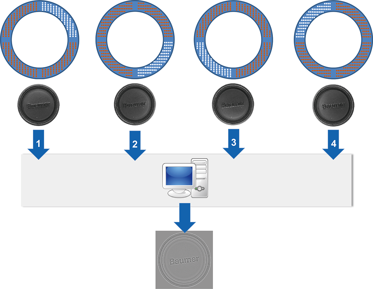
Surface quality inspection aims to identify shape deviations and structure irregularities of objects. For rapid examinations with maximum reliability, the object to be examined is illuminated from various directions and the resulting shadows are imaged and subsequently processed and evaluated. This approach is called “drawing shapes from the shadows” It is called (SfS).
Baumer CX.I cameras have pulse width modulation and four separate power outputs providing up to 120 W of power (max. 48 V / 2.5 A). When used with the sequencer, these four outputs provide easy quadruple lighting control, following the principle of extracting shapes from shadows.
Output Configuration
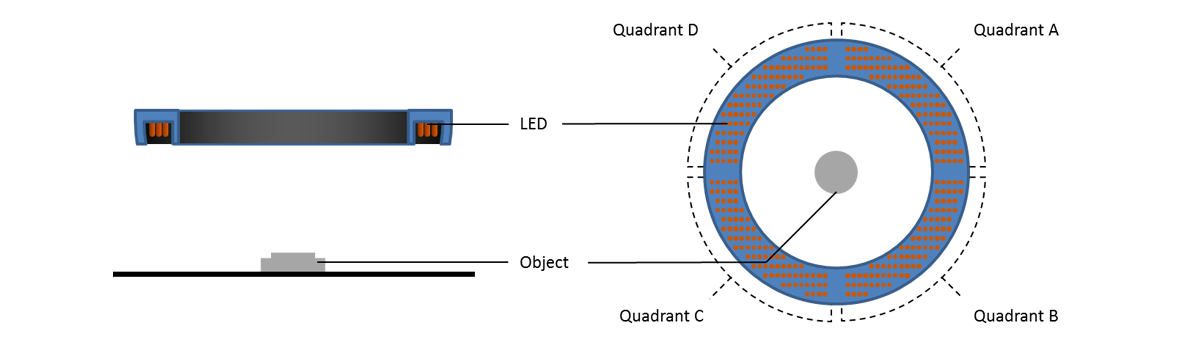
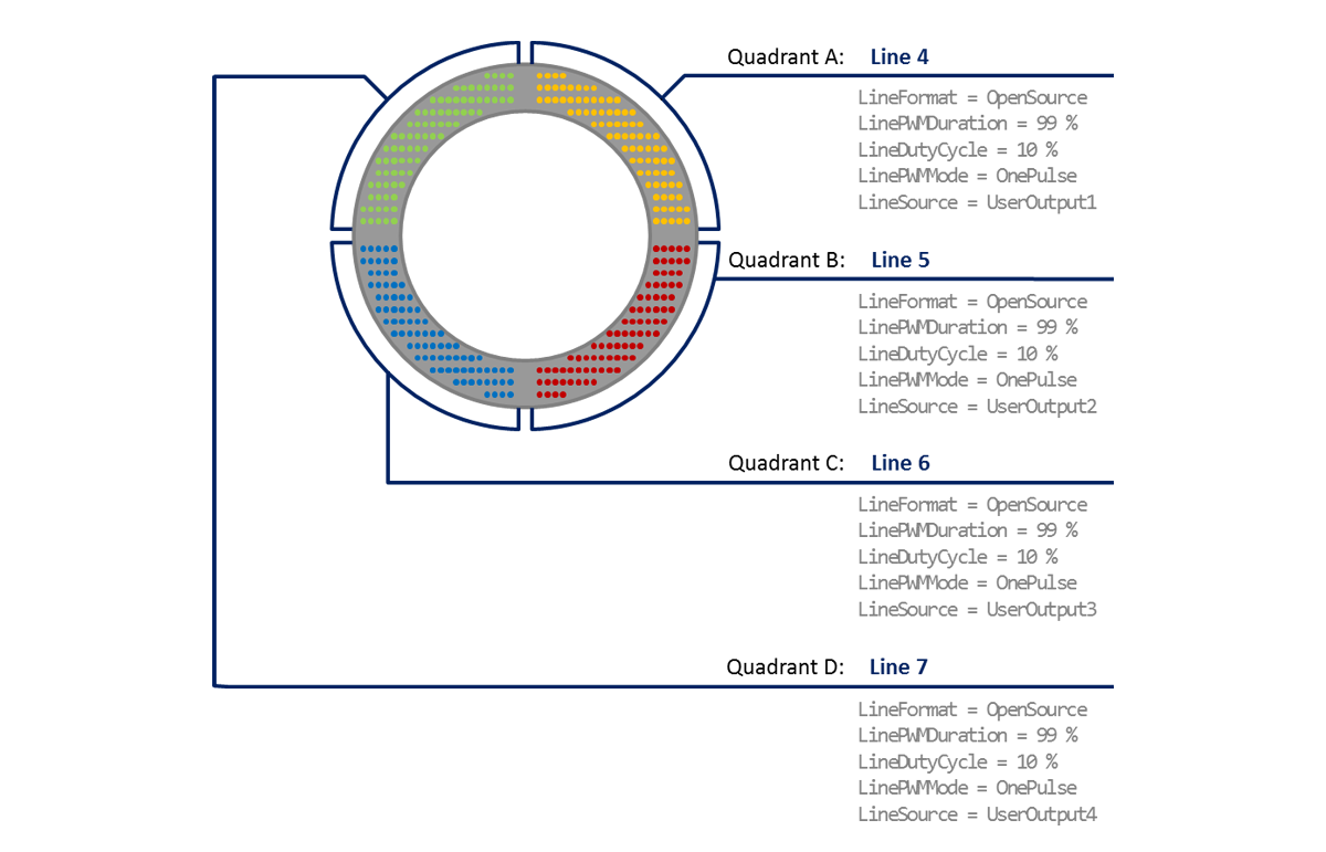
Each quadrant of the ring lighting must be configured. To avoid errors, all four quadrants should use the same configuration.
Attention
Please note the general information regarding commissioning, maximum load capacity and output configuration found in the camera user manual.
Expected Camera Behavior
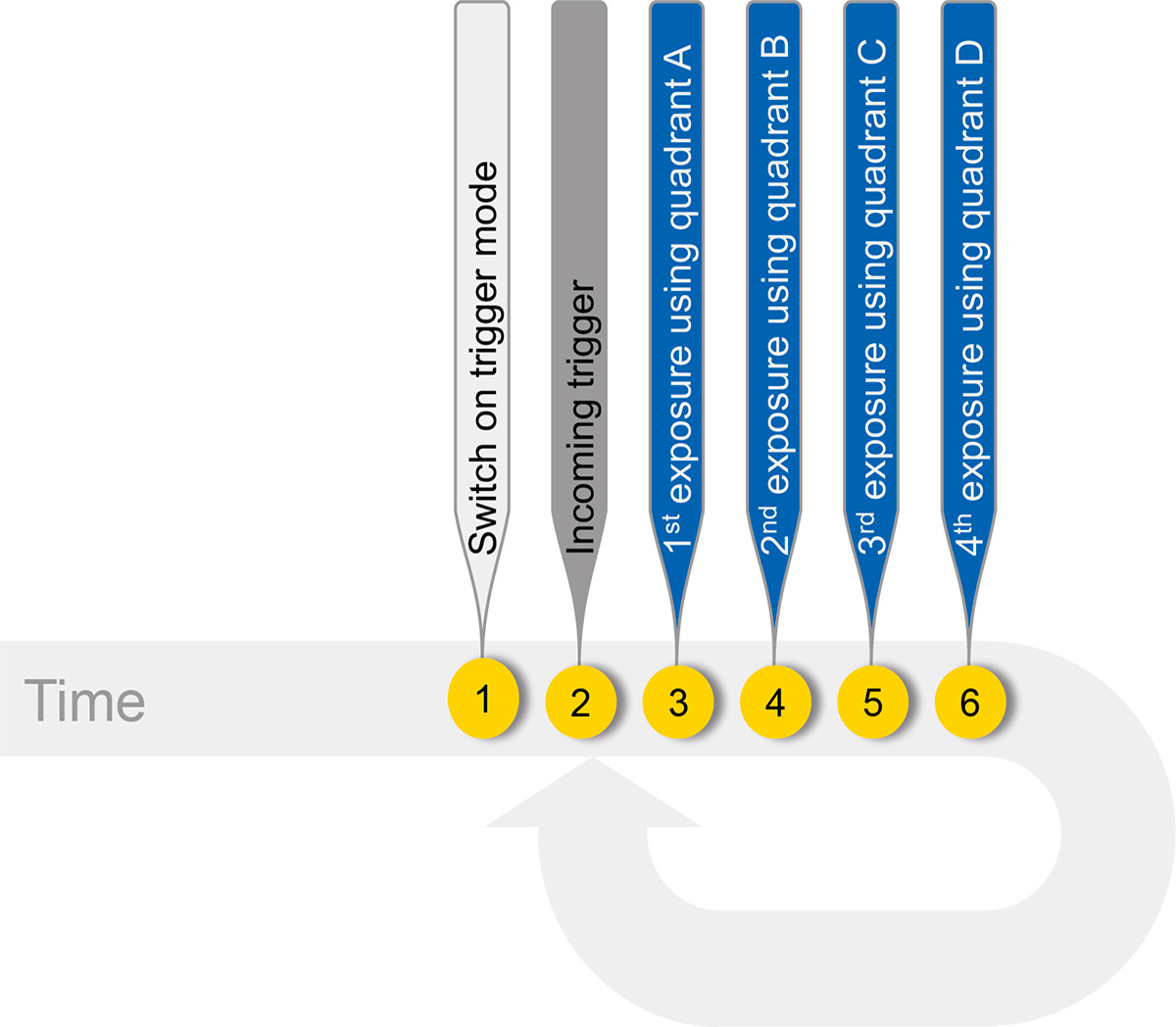
The shape extraction from shadows (SfS) technique requires the camera to be in trigger mode. Four images are taken with an incoming trigger signal. With each captured image, the corresponding dial is replaced by the assigned camera output.
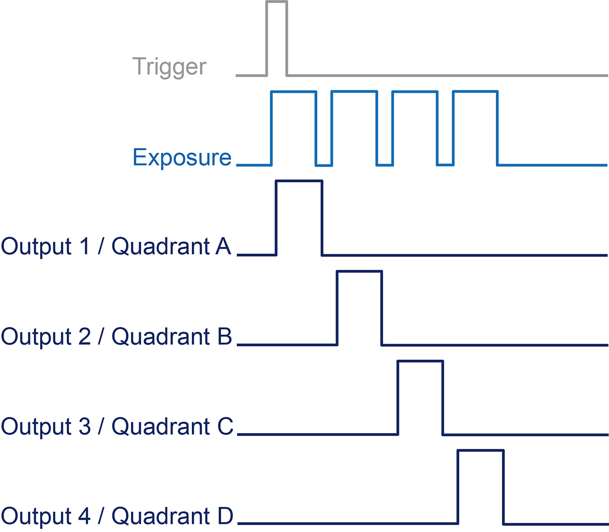
Sequence Timeline
The sequencer configuration for extracting shapes from shadows is as shown in the example below, considering basic sequencer principles.
- The acquisition of the first image is triggered by the hardware, followed immediately by the remaining three images, so an idle state is inevitable.
- Each image is associated with an individual illumination, which must be controlled by several sets of sequencers:
- First set of sequencers to activate illumination at the beginning of exposure
- Second set of sequencers to turn off illumination at end of exposure
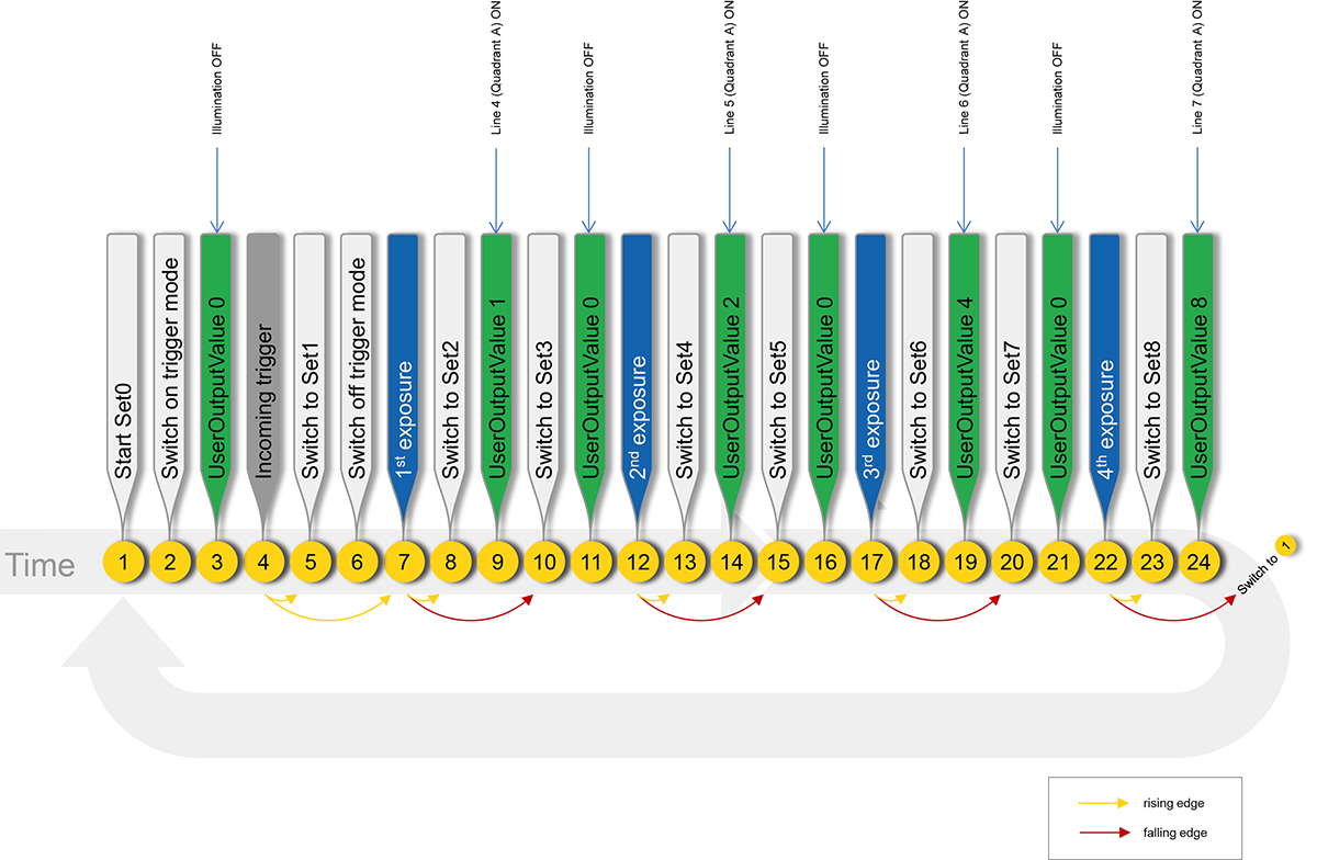
Application
Since the sequence must be started by a trigger, aTriggerSourcemust be defined. In this example, this resourceline0It is defined as . The trigger signal enters from this source.
Outputs/Lighting Control
The mapping of the camera's individual output states (Lines) is in binary format, but the parameter configuration is done in hexadecimal format.
| Line 7 | Line 6 | line 5 | Line 4 | Binary Value | UserOutputValue (Hex Value) | |
|---|---|---|---|---|---|---|
| All Lines CLOSED | 0 | 0 | 0 | 0 | 0000 | 0 |
| Line4 ON, other Lines OFF | 0 | 0 | 0 | 1 | 0001 | 1 |
| Line5 ON, other Lines OFF | 0 | 0 | 1 | 0 | 0010 | 2 |
| Line6 ON, other Lines OFF | 0 | 1 | 0 | 0 | 0100 | 4 |
| Line7 ON, other Lines OFF | 1 | 0 | 0 | 0 | 1000 | 8 |
| All Lines OPEN | 1 | 1 | 1 | 1 | 1111 | F |
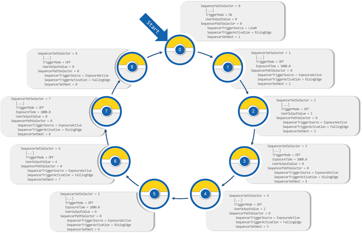
Sequence Set 0
The first set of sequencers is the waiting set. At this point, the camera waits for the incoming trigger signal and illumination is disabled (UserOutput Value = 0). The rising edge of the trigger signal is used to start the first exposure and switch to the second set of sequencers.
Sequencer Set 1
In the second sequencer set, TriggerMode is disabled. About the first imageExposureActiveThe rising edge of the signal is used to move to the next sequencer set.
Sequencer Set 2
In this sequencer set, the Line4 output is activated, i.e. the illumination of dial A is active. (UserOutputValue is set to 1.) Regarding the first imageExposureActiveThe falling edge of the signal is used to move to the next set of sequencers.
Sequencer Set 3
This sequencer set disables the illumination of the A dial at the end of the first exposure.
Sequencer Set 4
In this set of sequencers, the Line5 output is activated, meaning the illumination of the B quadrant is also activated. (UserOutputValue is set to 2.) Regarding the second imageExposureActiveThe falling edge of the signal is used to move to the next set of sequencers.
Sequencer Set 5
In this sequencer set, the illumination of the B quadrant is disabled at the end of the second exposure.
Sequencer Set 6
In this set of sequencers, the Line6 output is activated, meaning the illumination of the C dial is also activated. (UserOutputValue is set to 4.) Regarding the third imageExposureActiveThe falling edge of the signal is used to move to the next set of sequencers.
Sequencer Set 7
In this sequencer set, the illumination of the C quadrant is disabled at the end of the third exposure.
Sequencer Set 8
In the last set of sequencers, the Line7 output is activated, meaning the illumination of the D dial is also activated. (UserOutputValue is set to 8.) About the fourth imageExposureActiveThe falling edge of the signal is used to switch to sequencer set 0.
Conclusion
Four separate images of the object under examination are transmitted successively to a computer, where they are combined to form a single image. This merged image is used to examine the surface quality and indicates any shape or structure mismatches. In this way, surface defects and irregularities can be clearly detected.