Thermal Coupling of Industrial Cameras and VeriSens Image Sensors [AN201806]
Baumer industrial cameras and VeriSens image sensors
This document explains why body temperature rather than ambient temperature is specified in the data sheets of Baumer industrial cameras (hereinafter referred to as cameras) and image sensors. We also make recommendations on camera holder design for best heat dissipation.
Background Information
Reproducible image quality and high repeat accuracy are very important in image processing applications. That's why Baumer digital industrial cameras and image sensors are designed for reliable 24/7 operation.
Achieving specified quality, producing repeatable results and maintaining flawless system operation depends on many factors. One of these factors is quite dominant: Operating Temperature.
Contrary to popular misconception, operating temperature does not mean environmental or installation temperature. Instead, it refers to the temperature at a specific measurement point on the camera body. So why is this so?
Temperature Specifications in Datasheets
Storage Temperature
As is true for electronic devices, temperature specifications refer to the temperature inside the device. Looking at the relevant component specifications, one might think that the maximum limit is easy to determine.
Operating Temperature
However, the situation is different when it comes to image processing. The large number of parameters, component arrangements and environmental conditions make it difficult to draw a conclusion about the maximum environmental temperature based on the core temperature of the components.
Depends on core temperature, power consumption, thermal coupling and component interaction. The operating mode and load affect the power consumption of components such as sensor, FPGA, interface chip modules, etc., resulting in different core temperatures.
Reliable operation requires observing the maximum limit of thermal stress applied to electronic components. Temperature tests performed during development determine the maximum limit at a specific measurement point on the camera body.
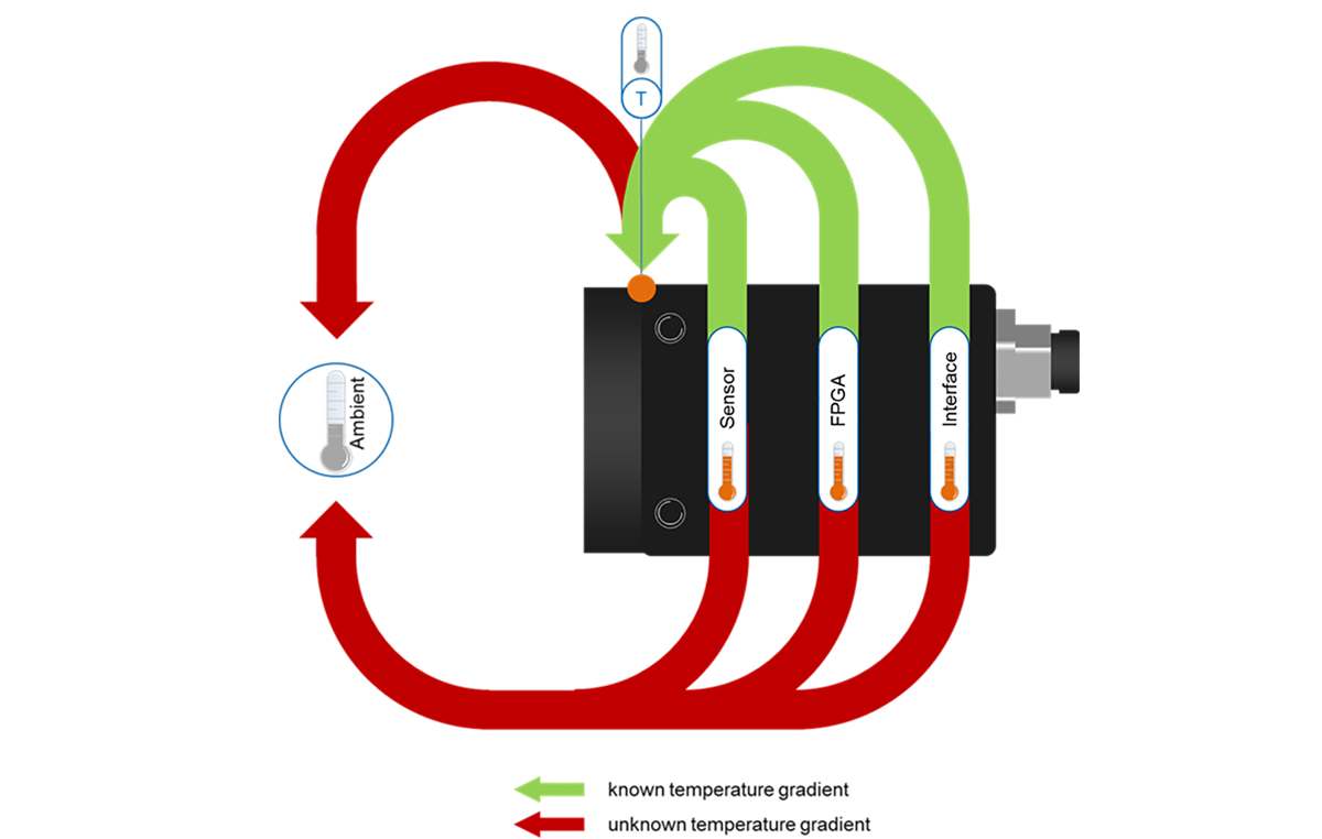
The temperature gradient between the outer and inner surface is known – At least you can use the device without any thermal coupling or temperature-related precautions, i.e. 'worst case scenario'. when operating under .
As previously mentioned and shown in the figure, no conclusions can be drawn neither between the temperature measurement point on the outer surface of the body and the environmental temperature, nor between the component core temperature and the environmental temperature.
This is due to many unknowns regarding the direct environment of the camera or image sensor:
- What is the thermal mass of the assembled component?
- What is the heat capacity of the assembly?
- How long does it take for the assembly to thermally stabilize?
- How is the component assembled?
- What is the geometry of the holder?
- What material is it made of?
- Is there any ventilation in the surrounding area?
Heat Dissipation in Cameras and Image Sensors
The heat produced in the device spreads in all directions. Heat conduction occurs on surfaces that are in contact with other components of the system. On the remaining surfaces, heat is dissipated from the camera by radiation and convection (see Figure).
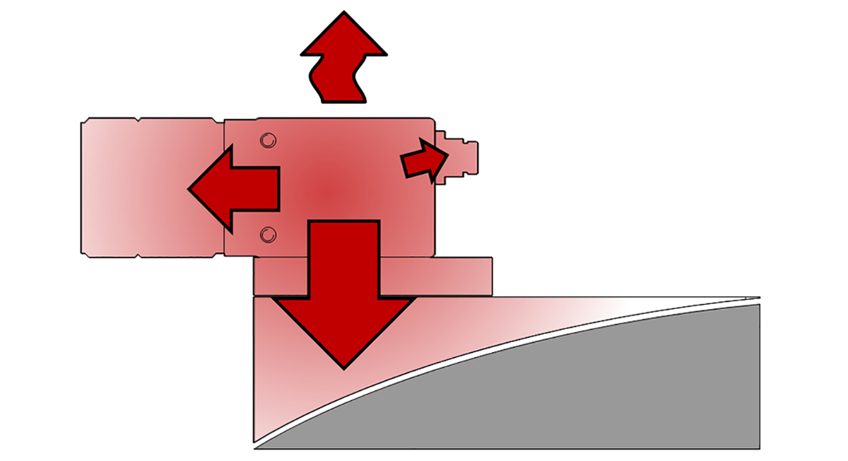
The lens and cables absorb some of the heat, but most of the heat is carried through the camera mount.
Thermal Connection
Temperature tests at the design stage are performed without thermal coupling. This type of “worst case scenario” conditions do not represent actual installation or operating conditions.
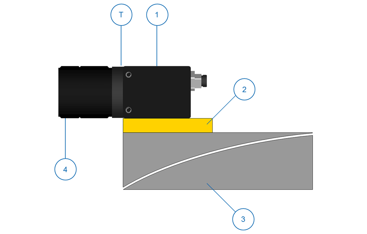
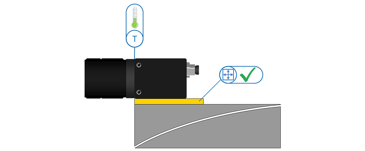
The figure shows that the camera (1) and the optics (4) are mounted on a metal contact surface (3) with the camera holder (2) in between.
Since most of the heat generated is dissipated through the device holder, this holder is the central element of the thermal coupling.
Design Suggestions for Camera Holders
Material
High conductive material is ideal, while low conductive material hinders heat dissipation.
note
Choose a good conductive material, for example aluminum, copper or brass. Do not use insulating materials!
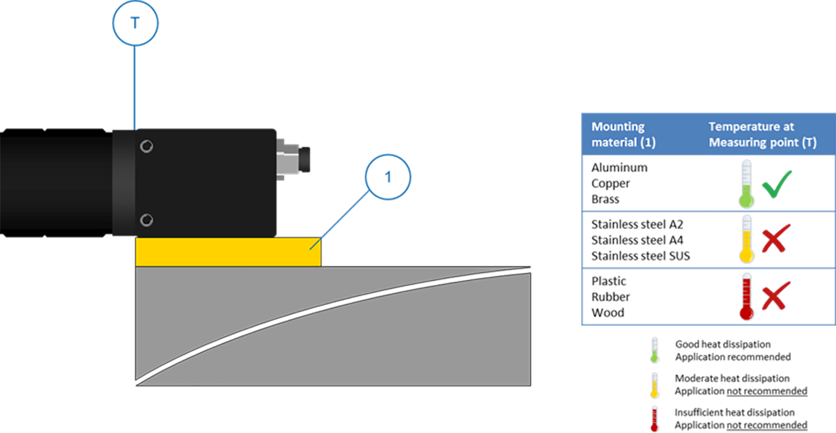
Design Geometry
Besides the actual material, the design geometry of the camera mount also significantly affects heat dissipation. Besides the thermal conductivity of the material, the contact surfaces of the camera, holder and mount directly affect the thermal resistance and therefore heat dissipation.
Material Thickness
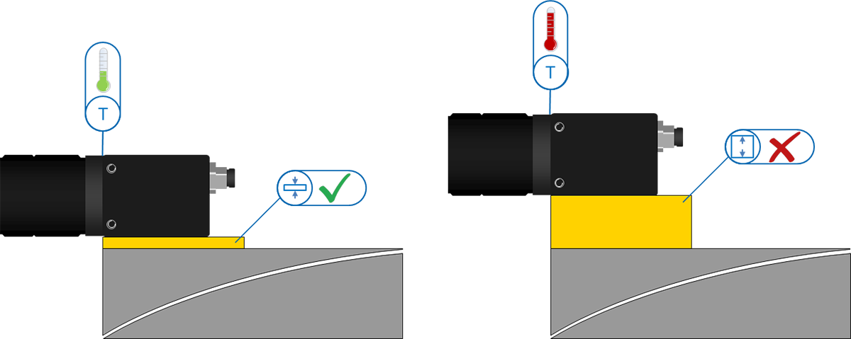
Surfaces with Good Thermal Conductivity
Because thin materials conduct heat very well, the holder should be as thin as possible to minimize the conduction path between the camera holder and the mount.
Installations and Machines with Insulating Surfaces (e.g. plastic)
In these cases, camera holders can act as a buffer, improving heat dissipation:
- By absorbing a certain amount of heat and retaining it for a short time,
- By dissipating heat through a poorly conductive surface larger than the surface of the camera.
Extra cooling is recommended, for example with active cooling elements or ventilation.
length

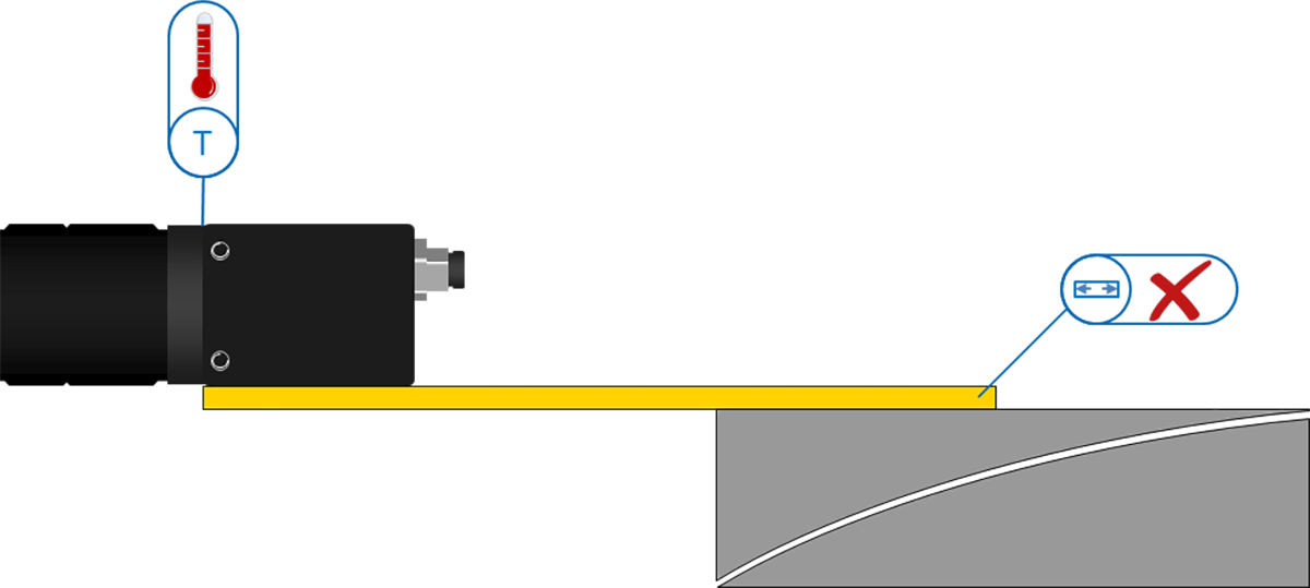
Thermal Connection on Highly Conductive Surfaces
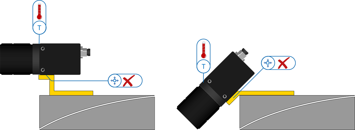
Provide a short holder design to keep the conductive path between the camera and the mount as short as possible.
Thermal Coupling on Low Conductive Surfaces (e.g. plastic)
In these cases, camera holders can improve heat dissipation by:
- By absorbing a certain amount of heat and retaining it for a short time,
- By dissipating heat through a larger surface.
Extra cooling is recommended, for example with active cooling elements or ventilation.
Contact Surface
Camera holder design must provide sufficiently large contact surfaces between the camera, holder, and mount. The camera must rest completely on a side surface.