Use of General Purpose Inputs/Outputs (I/O) with Programmable Logic Controllers (PLC) [AN201704]
Baumer Cameras: VCXx, MXU
This document describes an approach to changing/amplifying the GPIO output level of a camera to interact with the input of a PLC.
Technical Background
In industrial environments, such as automation technology, control and synchronization of cameras and other components such as sensors and actuators are accomplished with programmable logic controllers (PLC). Higher switching levels compared to transistor-to-transistor logic (TTL) increase the electromagnetic noise immunity of both inputs and outputs, thus increasing the interference resistance of the entire application.
TTL and PLC Switching Levels:
| Status | TTL switching levels | PLC switching levels |
|---|---|---|
| high | 2.8V to 5.0V | 11.0 V to 30.0 V |
| restricted area | 0.8V to 2.8V | 4.5V to 11.0V |
| low | 0.0V to 0.8V | 0.0 V to 4.5 V |
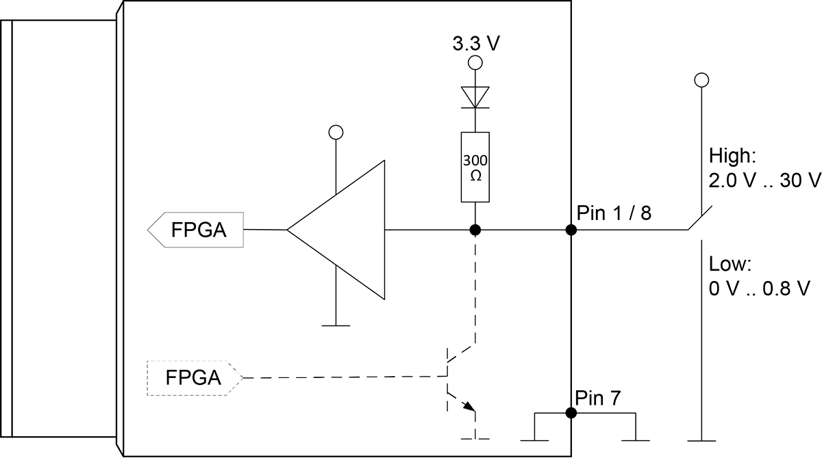
On the input side, general-purpose I/Os generally have high levels between 2.8 V and 30.0 V and are therefore suitable for operation in conjunction with a PLC.
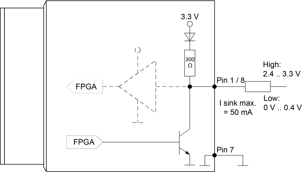
On the output side, the situation is different because the high levels of general-purpose I/O are typically 3.3 V, but PLCs only detect levels of 11.0 V or higher.
GPIO Connection Diagrams
Solution
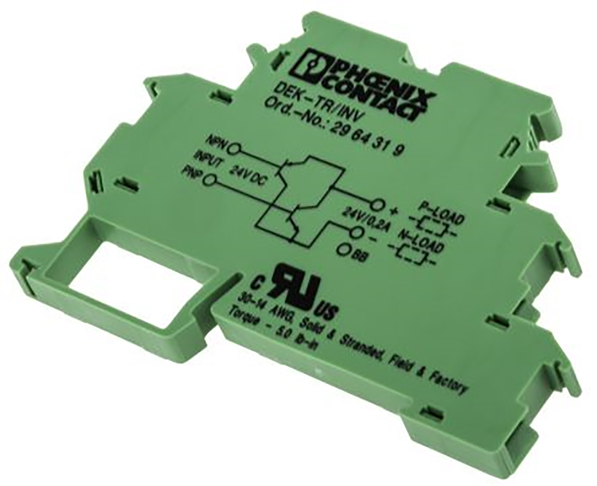
Phoenix Contact DEK-TR/INV (Part Number 2964319) is a switching amplifier used to raise the high level of the GPIO from 3.3 V to 11.0 V or more, a PLC-compatible switching level.
Thanks to the DIN rail design, this module can be easily placed between the camera output and the PLC input.
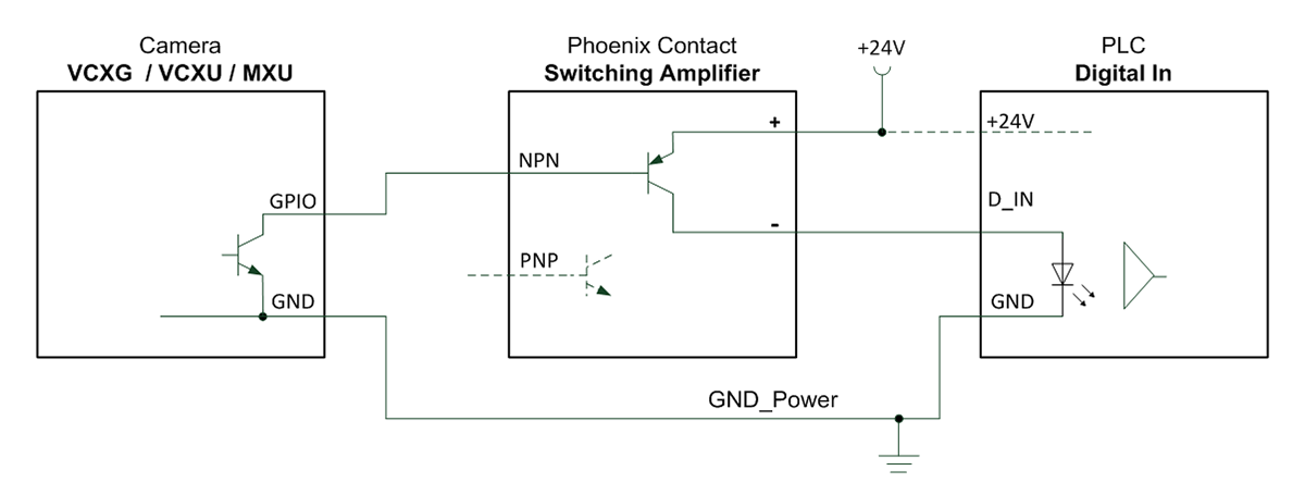
The figure below shows the connection diagram of the DEK-TRI/INV switching amplifier connected to the GPIO and digital PLC input of a Baumer VCXG, VCXU or MXU camera.
In this connection, since the camera's output operates in active-low mode, the line inverter of the output must be activated.