Installation of Voltage Sensors
In Which Applications Are Strain Sensors Used?
Strain sensors are used as a smart alternative to force sensors for large forces above 10,000 N and are involved in a variety of applications. A few examples are presented below. Additional application examples can be found on the strain sensors product website.
Strain Measurement in Industrial Applications:
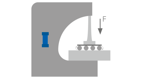
Holding Force Regulation
The plate is held with the necessary force so that it can move at maximum speed without slipping or creating marks.
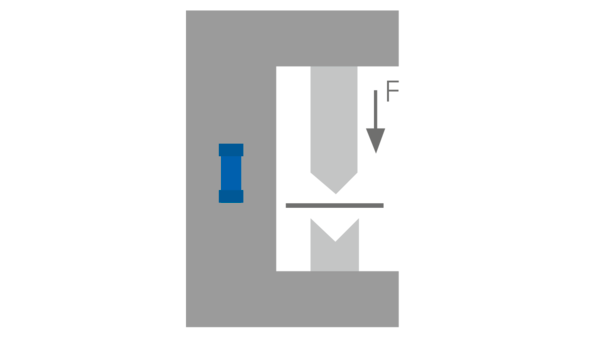
Process Control
During the bending process, the force is controlled throughout the entire process and this is used to improve or maintain the process.
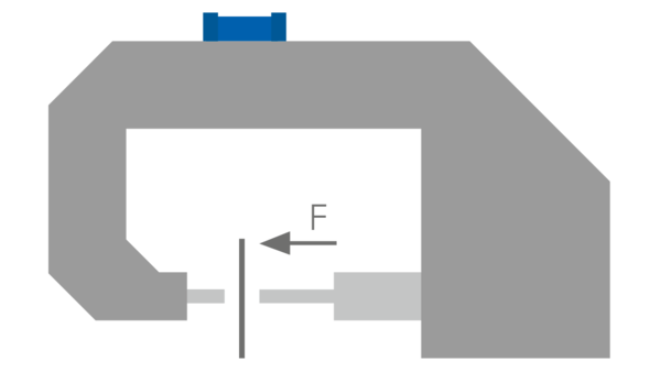
Force Monitoring During the Joining Process
Continuous force monitoring throughout the joining process ensures that the joint created can meet high stability and durability requirements.
Strain measurement in demanding outdoor applications:
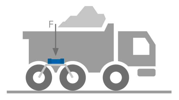
Weight Measurement of Construction Vehicles
With the help of strain sensors, the weight of construction vehicles is determined. For example, overloading is avoided by controlling the loading of dump trucks.

Vibration Damping
Strain sensors can be used to dampen vibrations in construction machinery. For example, it is used to reduce vibrations in the placing boom of truck-mounted concrete pumps.
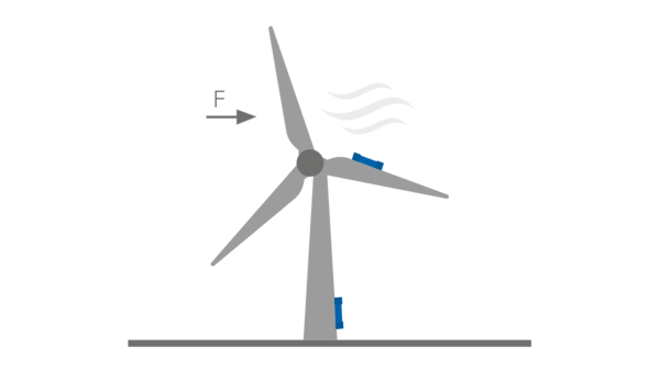
Load Monitoring of Wind Turbines
Using strain sensors, loads on towers or rotor blades in wind turbines are reliably monitored. In this way, overloads are detected and turbine damage is prevented. The service life calculated on the basis of actual loads is extended.
Selection Criteria for Strain Sensors
To find the right strain sensor, it is necessary to take into account a number of criteria. The selection starts first with the application environment; sensors can be used for harsh outdoor applications or industrial indoor applications. The structural properties to be monitored determine whether screw strain sensors or through-hole sensors are more suitable. Available space is also important; There are solutions for limited space conditions. The measurement range should be selected according to the expected strain. Most strain sensors have integrated amplifier electronics, making it easy to choose standard signals. The sensors are fatigue resistant and ideal for cyclic and static applications. It should be noted that external factors, especially temperature changes, can degrade the signal, but there are measures to compensate for these effects.
Where to Place Strain Sensors?
Screw strain sensors can detect very small strains in the micrometer range caused by the force applied to the structure and can be easily installed. To find the optimal location for a strain sensor and obtain the best results, some points should be taken into account.
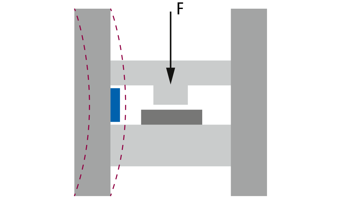
Strain sensors should be placed in locations where measurable strains due to the force applied to the structure can be expected. These strains are usually caused by bending or tensile/compressive stresses. For multiaxial strain cases, the expected surface strain and direction can be determined using the finite element method. If this is not possible, the actual strain at the selected point can be determined by experimenting with a strain sensor with a larger measuring range (e.g. 750 or 1000 µm/m). Factors such as structure design, accessibility and sensor protection also play an important role in sensor positioning.
What Strains Are Appropriate for Positioning?
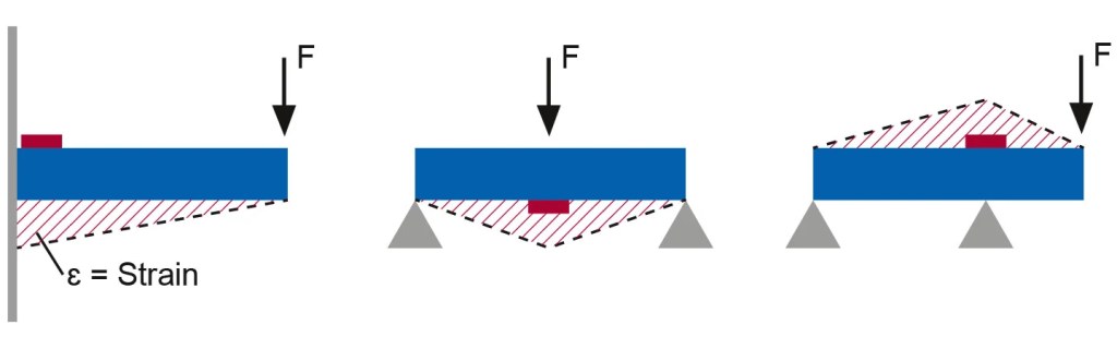
Strain Through Bending:
When installing strain sensors, it is easy and therefore convenient to determine the surface strains due to bending. The diagrams below show some points where the largest measurable strains for bending can be expected.
Strain Due to Tensile or Compressive Stresses:
Usually a monitored machine undergoes bending, tensile/compressive stress, torsion, etc. They exhibit combined strains such as These strains can be easily determined by finite element calculation. However, in practical application, a simple mechanical evaluation is sufficient to determine the appropriate points of the structure. Exact strains can be determined by comparing measured strains with known stresses. It is also possible to first affix strain gauges at points of interest to facilitate proper positioning of the strain sensor.

Usually a monitored machine undergoes bending, tensile/compressive stress, torsion, etc. They exhibit combined strains such as These strains can be easily determined by finite element calculation. However, in practical application, a simple mechanical evaluation is sufficient to determine the appropriate points of the structure. Exact strains can be determined by comparing measured strains with known stresses. It is also possible to first affix strain gauges at points of interest to facilitate proper positioning of the strain sensor.
What are the advantages of limited stiffness strain sensors?
Most Baumer strain sensors have limited stiffness mechanisms. This means that only a small force is required to reach the rated voltage of the sensor. Therefore, the strain sensor has a limited effect on the structure to be monitored. Additionally, the mounting screws have limited strain, resulting in stable signal quality without potential movement of the screws. This is important in cases where the strain sensor cannot be calibrated cyclically. These features make Baumer strain sensors suitable for both static and cyclic applications.
How to Install Strain Sensors?
For optimal measurement results, the strain sensors are screwed into the component using the supplied mounting screws. The strain sensor detects strains in the micrometer range via a frictional joint. Blind holes or clearance holes can be used. Also see the mounting options section. Screwing in durable strain sensors ensures consistent quality, without the need for laborious application of glue-on strain gauges.
What Should Be Considered When Installing Strain Sensors?
In order for strain sensors to detect surface strains precisely and provide good measurement results, various external conditions must be taken into account during installation. These conditions can be found in the operating instructions for each strain sensor. The installation surface plays a big role. The strain of the base structure is transferred to the strain sensor via a frictional connection.
What Mounting Options Are Available?
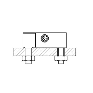
Option 1:Strain sensors can be fixed to the structure to be monitored with mounting screws in clearance holes.
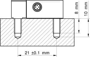
Option 2:In thinner structures, strain sensors can be fixed in through holes using nuts.
Preparation of the Mounting Surface
Important:
The measurement results of the sensor will not be accurate if the measuring surface is dirty or incorrectly mounted:
- Prevent contamination with oil and grease.
- Mount the sensor on a prepared, flat surface.
- Pay attention to surface roughness.
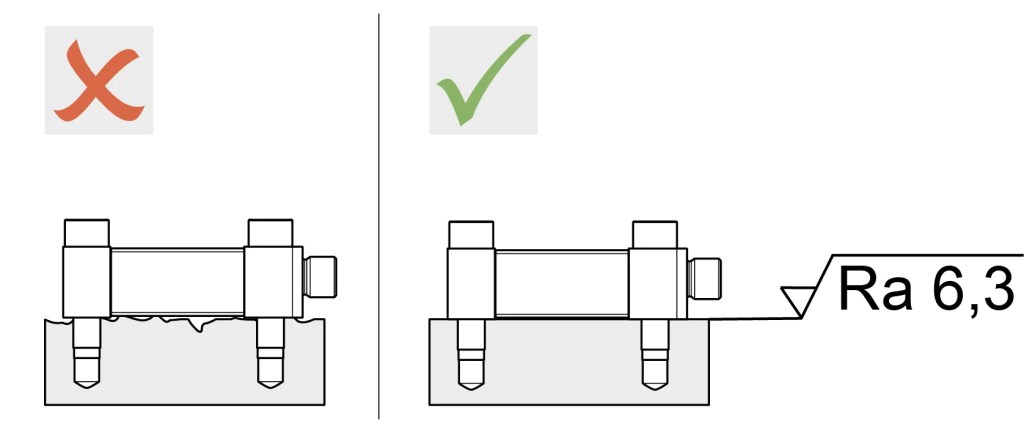
- Check Surface Roughness
- Ra ≤ 6.3 µm
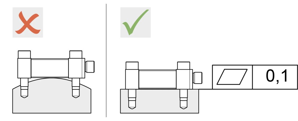
- Check Flatness Tolerance
- Flatness tolerance ≤ 0.1 mm
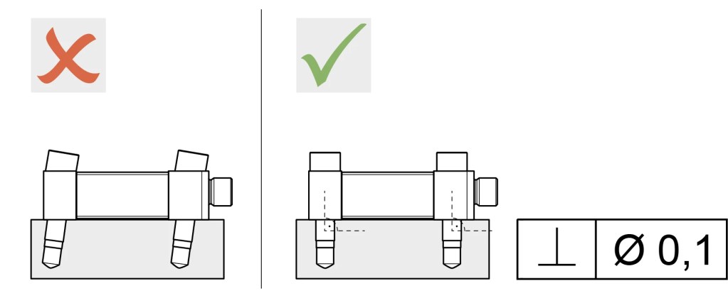
- Ensure Verticality of Holes
- Make sure the holes are drilled perpendicular to the contact surface of the sensor.
The relevant mounting screws, hole distances and diameters are listed in the operating instructions.
option:
If it is difficult to prepare the mounting surfaces to the required quality, ball wedges can be used to compensate for some roughness or angular hole deviations.
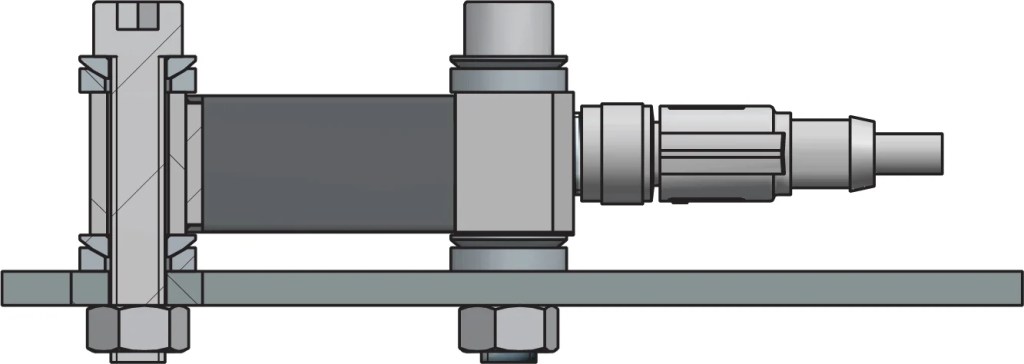
Diamond-coated friction mounts are also available on the market, which compensate for slight irregularities and increase friction.
How Should Strain Sensors Be Used?
Strain sensors are precision measuring sensors that contain factory calibrated mechanisms. The sensor may be damaged if dropped while unpackaged. Observe the notes in the user manual for instructions on storage and transportation.
How to Place a Strain Sensor?
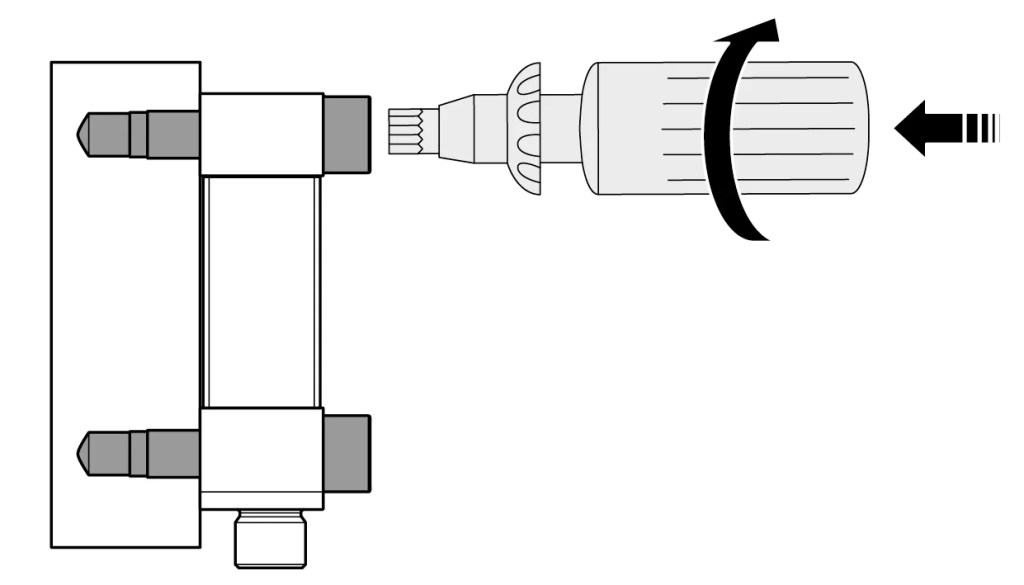
- Make Sure the Machine Element Is Not Under Stress: Make sure that the machine element is not under stress during assembly.
- Hand Tighten Mounting Screws: Tighten the screws by hand.
- Use a Torque Wrench: Tighten the mounting screws with hex sockets using a torque wrench. The relevant tightening torque can be found in the operating instructions.
Things to Consider in Case of Strains Caused by Thermal Expansion
Strain sensors are designed to measure strains caused by mechanical force and should not be affected by thermal expansion. When affected by heat, an object expands in all directions. Proper circuit arrangement of strain gauges within the sensor compensates for thermal expansion. The sensors are compensated for the thermal expansion of the steel. Make sure that the thermal distribution at the selected point is as even as possible. This properly compensates for temperature effects.
Thermal expansion:

Example thermal expansion coefficients α:
- Chromium nickel steel CrNi 80 20: α = 15.5 x 10⁻⁶ [K⁻¹]
- Chrome steel 13 Cr: α = 11 x 10⁻⁶ [K⁻¹]
- Pure aluminum: α = 23.8 x 10⁻⁶ [K⁻¹]
Examples:
- Chrome nickel steel bar CrNi 80 20, 20°C to 70°C, initial length 1 m.
∆l = lo x α x ∆T = 1000 mm x 15.5 x 10-6[K-1] x 50K = 0.775mm
This is equivalent to 775 µm/m. - Aluminum rod, 20°C to 70°C, initial length 1 m.
∆l = lo x α x ∆T = 1000 mm x 23.8 x 10-6 [K-1] x 50 K = 1.19 mm
This is equivalent to 1190 µm/m.
Therefore, if you want to monitor an aluminum structure with a strain sensor compensated for steel, you must compensate for thermal expansion to measure only the strain resulting from mechanical effects. However, if calibration can be done after each mechanical stress cycle, thermal expansion effects can be neglected.
Other temperature compensation methods:
- Compensation for thermal effects by 90° placement of strain sensors or temperature measurement on the component.
How to Calibrate Force in the System?
The resulting force for a given strain can be calculated mathematically or by comparison with a given force. For this, the strain sensor is screwed into the unstressed structure and then calibrated. The structure is then subjected to a known load or defined force. This provides the connection between strain and the force resulting from that strain. This calibration should only be done once for each system. Since Baumer strain sensors are adjusted for strain during production, they give the same measurement values when replaced.
How to Achieve Stable Measurements with Strain Sensors?
Screw the strain sensor into place and allow the sensor to warm up according to the instructions for use. (Measurements made with an unscrewed sensor do not give stable results). Initial settlement can be minimized by subjecting the structure to be monitored to maximum stress 10 times. When the structure is stress-free, the sensor must be calibrated to the amplifier. In this way, signal changes due to mounting can be compensated.
When Should Strain Sensors Be Calibrated?
Calibration After Assembly:Strain sensors must be calibrated after being mounted on the amplifier. This compensates for signal changes due to mounting.
Calibration During Operation:In cyclic processes, it is recommended to calibrate the strain sensor after each cycle while the machine is stress-free. This compensates for temperature effects or slight movements in the mounting screws. Baumer strain sensors feature soft measuring mechanisms that ensure stable static measurements even without cyclic calibration.
What Does a Measuring Chain for Strain Sensors Consist of?
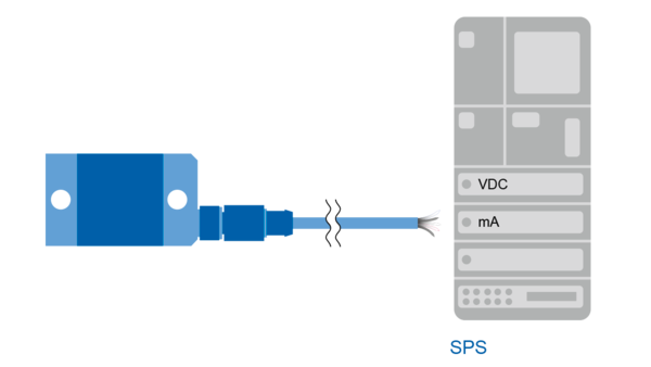
Strain Sensors with Integrated Amplifier Electronics:
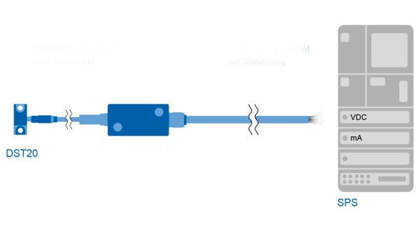
Strain sensors with separate amplifier electronics:
Passive strain sensors directly connected to a control unit with integrated amplifier:
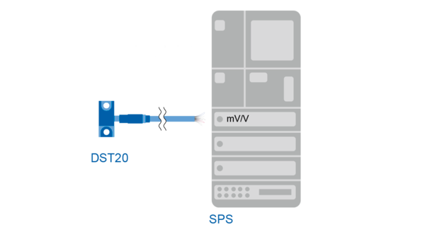
Important: The connecting or splicing cables must have the same degree of protection as the strain sensor. For example, for DST55R with IP69K protection rating, cables with IP69K rating must be used.