Installation of Light Barriers and Diffuse Sensors
Assembly and Installation
Installation of Diffuse Sensors with Background Suppression
The diffuse sensor must be pointed at the object. The detection distance should be set to a distance between the target and the background. The background must be at least as far behind the set detection distance as the sensor's detection distance reduction distance against black.
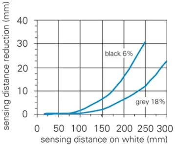
For diffuse sensors with background suppression, the sensing distance diagram is indicated for optimum setting. This shows the detection distance reduction as a function of detection distance to white for different degrees of reflectance. This refers to how much the detection distance for black or gray is reduced compared to white. Once the set detection distance to white is entered on the X axis of the diagram, the detection distance reduction to black or gray can be read on the Y axis. The detection distance reduction also indicates the minimum distance a black or gray object should be from a white background.
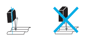
Direct reflection from shiny or reflective objects should not strike the receiver. This can be prevented by slightly tilting the sensor.
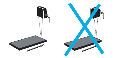
The object to be detected must be ensured to approach the active area of the sensor from the side, which prevents malfunctions that may occur due to deflection of the light beam at the edges.
Reflectorless Light Barriers
The SmartReflect light curtain must be aligned with a piece of machinery within detection range. This machine part is adjusted using teach-in.
It should be noted that there is a dead band just in front of the machine part, which is automatically adjusted during teach-in. The dead zone is defined by the detection range (Sa) and the background position (Sde) in percentage (%).
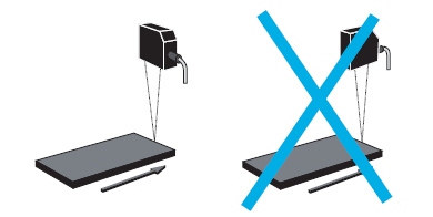
It should be noted that an object to be detected must approach the active area of the sensor from the side to avoid switching errors.
Diffuse Sensors with Different Density
In diffuse sensors operating on the principle of density difference, the relative receiver signal is specified. This represents the signal level received from a white object depending on distance. Using this diagram, the detection distance for a non-white object can be determined. For this purpose, the correction factor of the relevant material is required.
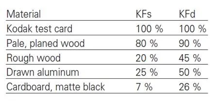
Correction Factor
The material and surface properties of the object (representing reflectivity) affect the switching distance of the diffuse sensor, which works on the principle of density difference. To determine the corrected switching distance, the following values must be applied to the relative receiver signal (KFs) or approximate distance (KFd).
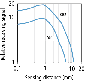
Retro-reflective Sensors
Each sensor has a separate excess gain curve. Since operational reliability is highly dependent on environmental conditions, it must be ensured that the sensor operates with the highest possible excess signal gain.
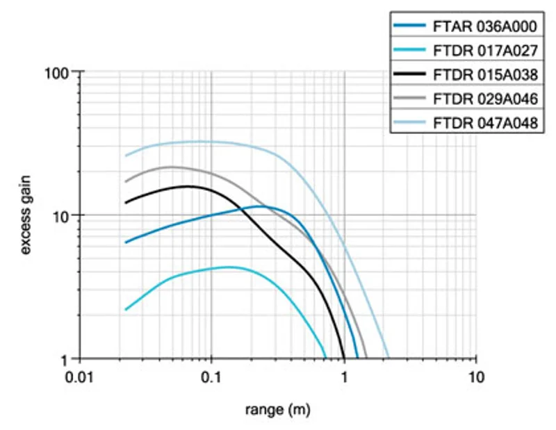
When narrow light beams are used, especially in laser sensors, the size of the light spot on the reflector and its position relative to the triplex structure is a critical factor when choosing the reflector or type of reflector. For spot diameters up to 1.5 mm, a special type of reflector or reflector for laser sensors must be used. For spot diameters up to 3 mm, it is recommended to use microstructured reflectors. It should also be noted that the type of reflector or reflector should not be placed close to the focal point.
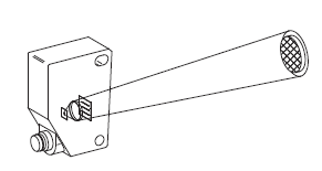
The reflector is aligned and centered.
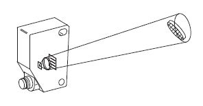
The reflector should not be tilted more than 15°.
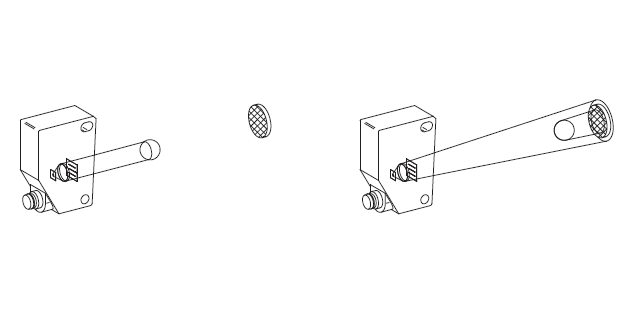
For correct function, the object must cover the reflector or be at least as large as the diameter of the light beam at the distance.
Mutual Light Barriers
The transmitter and receiver must be pointed at each other. The narrower the radiation and reception angle, the more precisely this straightening must be done.