Installation of Ultrasonic Sensors
Baumer ultrasonic sensors offer a high degree of flexibility in installation. The only prerequisite during installation is to ensure that no material accumulates in the sound beam area. Sound-absorbing materials such as cotton wool or soft foam rubber can reduce scanning distance. Liquids and solid materials are very good reflectors of sound.
Minimum Distances
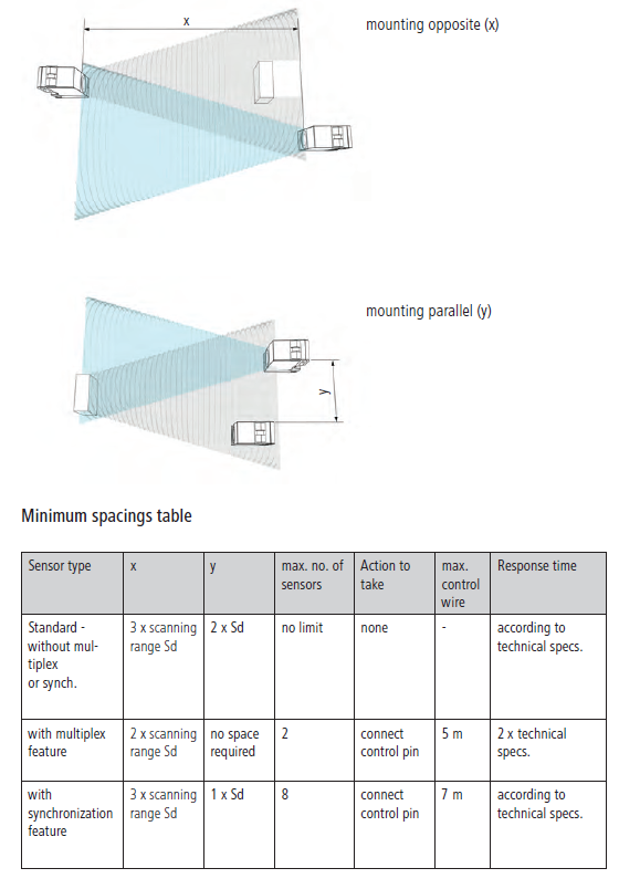
To prevent the sensors from affecting each other, a certain distance must be maintained between the sensors, depending on the sensor type:
Synchronization or Multiplexing Feature
The minimum distance may not always be maintained in all applications. For this purpose, sensors with synchronization mode are used. Such sensors synchronize the transfer cycles of individual sensors in order to reduce the minimum distance.
Synchronization Feature
Connect the control pin of all sensors within a limited area. This triggers all sensors to measure simultaneously. Due to the longer detection distance, any interference signals reaching the sensor later are ignored. Up to eight sensors can be synchronized via the control pin.
Multiplexing Feature
Connect the control pin of both sensors together. While the first sensor is making measurements, the second sensor is disabled. After the first measurement is completed, the second sensor can send and receive signals. A maximum of two sensors can be connected together. The multiplexing function increases the sensor response time to twice the specified value.
Note: In sensors using synchronization or multiplexing, the control pin must be closed. If the feature is not used, the standard response time must be achieved by connecting the pin to the following potentials:
- synchronization: Connect the control pin to the supply voltage (+Vs).
- multiplexing: Connect the control pin to ground (GND).
Setup Help
The LED indicates the intensity of the signal reflected by the object and the switching status of the output.
LED on
The object is detected reliably with a 50% signal power reserve. The output is active/switched.
LED off
Target not detected, output inactive/unswitched.
LED flashing
Unreliable detection of the target. The output is active/switched.
Teaching (Teach-in)
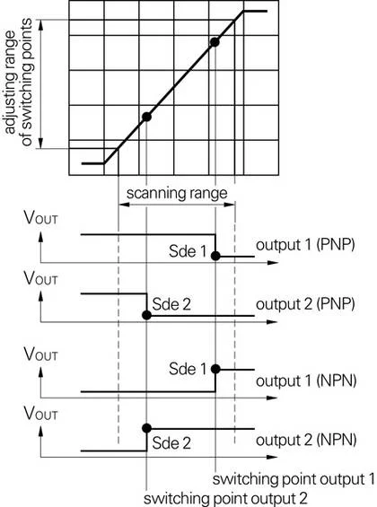
Ultrasonic sensors are similar to the standard range with a "Teach-in" function, but offer additional flexibility with a simple touch-key setup. Switching points (Sde 1 and Sde 2) can be easily programmed within the detection range with the built-in Teach-in button.
General Settings
Teach-in lock
Teach-in lock is activated 5 minutes after power-on or after the last teach-in. Teach-in lock is reset by disconnecting the power supply. The teach-in lock can be released by briefly turning off the main power.
Resetting to original factory settings
Holding the button for more than 6 seconds automatically restores the original factory settings. Fast flashing of the green/yellow LED indicates that the reset has been completed successfully.
Adjusting Ultrasonic Proximity Switches
Switching points (Sde 1 and Sde 2) can be easily programmed within the detection range using the built-in Teach-in button.
Setting Switching Point Sde 1
- Adjustment mode: Press and hold the teach-in button for about 2 seconds, wait until the LED flashes green. Release the button.
- LED flashing green. Position the target at the desired scanning distance and press the Teach-in button.
- Confirming successful completion of the teach-in process: The LED lights for approximately 2 seconds.
Setting Switching Point Sde 2
- Adjustment mode: Press and hold the teach-in button for about 4 seconds, wait until the LED flashes yellow. Release the button.
- LED flashing yellow. Position the target at the desired scanning distance and press the Teach-in button.
- Confirming successful completion of the teach-in process: The LED lights for approximately 2 seconds.
Functional Diagram
Adjusting Ultrasonic Retro-reflective Sensors
Adjusting Sde Reflector Distance
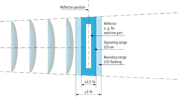
The potentiometer of the sensor allows the user to set the adjustment conditions for a specific reflector position (Sde). The output LED also functions as a tuning aid as follows:
- Reflector operating range
If the Sde setting deviates less than ±2.5% from the actual reflector position, the reflector is within operating range. LED is constantly on, the output is not active. - Reflector within limit range
Up to ±5% deviation, the output remains active but the LED blinks. This indicates that the Sde setting is not optimal and needs to be corrected.
All adjustments are made using the built-in Teach-in button.
Teach-in Adjustment of Reflector Position
Press and hold the Teach-in button for more than two seconds to enter setting mode. When the LED flashes green, it indicates that you have pressed long enough. When you release the button, the LED continues flashing. Each subsequent press of the button teaches-in the position of the reflector.
Settings of Ultrasonic Through Light Barrier Sensors
All adjustments can be made via the built-in Teach-in key.
Sensitivity Setting
LEDs indicate the sensitivity of the receiver. Sensitivity can be invoked at any time by pressing the Teach-in key, even with locked teaching functionality. Move the transmitter and receiver to the desired position.
Put the transmitter into setup mode by pressing and holding the teach-in button for about two seconds, wait until the green LED starts flashing. Release the teach-in button. The green LED now indicates the switching status. Press the Teach-in key repeatedly until you reach the desired sensitivity and the green LED is solid.
Sensitivity is indicated by yellow LEDs on the display.
To complete the teach-in process, press and hold the Teach-in key for about two seconds, wait until the green LED starts blinking rapidly. Release the teach-in button. LED turns off!
Response Time
To put the sensor into teaching mode, press and hold the Teach-in key for approximately four seconds, wait until the red LED starts flashing. Release the teach-in button. The red LED is constantly lit. Press the Teach-in key repeatedly until you reach the desired response time.
LED Display:
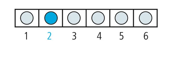
- LED off; approximately 5ms response time delay
- 1. LED is on; approximately 10ms response time delay
- 2. LED is on; approximately 20ms response time delay
- 3. LED is on; approximately 40ms response time delay
- 4. LED is on; approximately 80ms response time delay
- 5. LED is on; response time delay of approximately 160 ms
- 6. LED is on; response time latency of approximately 320 ms
To complete the teach-in process, press the Teach-in key for about two seconds, wait until the red LED starts flashing quickly. Release the teach-in button. The response time is now set.
Ultrasonic Distance Sensors with qTeach
qTeach
The new, comfortable and wear-free qTeach teaching method was developed and introduced by Baumer.
Teaching the O500 sensors is accomplished by touching them with any ferromagnetic tool. Blue LED light provides clear optical feedback. To prevent user errors, qTeach automatically locks after 5 minutes.
Setting with qTeach
Setting the 0 ... 10 V output function
Press and hold the Teach-in button for 2 seconds or more to put the sensor into Teach mode. Successful entry into teach mode is indicated by a flashing bi-colour LED. When you release the Teach button, the red LED starts flashing. Pressing the button once more teaches the near limit (Sdc), followed by the far limit (Sde). Lighting of the sensor LED for 2 seconds confirms that the teach-in process is complete. At this point you can set the close limit (Sdc) by placing the target at the desired distance from the sensor and confirm by briefly pressing the button or connecting the Teach-in wire with +VS. The LED flashes amber. Now you can program the far limit (Sde) by placing the target at the farthest desired distance from the sensor, confirm by briefly pressing the button or by connecting the Teach-in wire with +VS. Both LEDs will light for 2 seconds to confirm that the teaching process has been completed correctly.
Programmable Output Curve
optionally
Separate digital PNP output with a switching point that can be set using the teach-in function.
Inverting the Output Function to 10 ... 0 V
The sensor output signal can be inverted to 10 ... 0 V by first teaching the far limit (Sde) and then the near limit (Sdc).
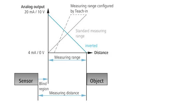
linearity
Deviations in linearity mostly occur within the sensor and due to changes in ambient temperature. Resolution, temperature drift, and repeatability define linearity error.
Minimum Load Resistance
When using a sensor with current output, the voltage drop across the load resistor is proportional to the current. To ensure correct operation of the output layer, do not exceed the maximum allowable load resistance specified in the data sheet.
resolution
It defines the smallest position change of the object that causes a voltage or current change at the sensor output.
Angular Deviation
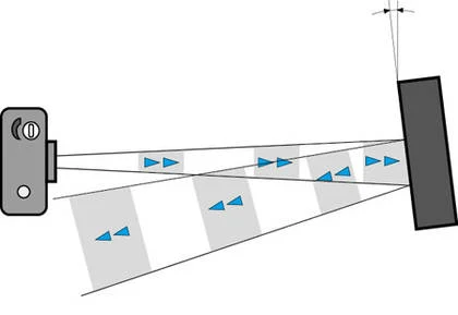
Like light waves, a flat surface reflects sound waves best – so an angled surface may not be sufficient for accurate target recognition. As the distance between the sensor and the target increases, the tilt effect also increases.
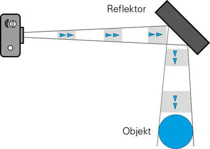
This can also be turned into an advantage when detecting a distant target, as shown in the figure. The reflector must be large enough and have smooth surfaces and edges.