Installation of Inductive Sensors
Assembly and Installation
Electrical Connection
Digitally switched sensors are available with PNP, NPN or Namur output; Measuring sensors, on the other hand, come with voltage output (0 … 10 V) or current output (e.g. 4 … 20 mA or 0 … 10 mA).
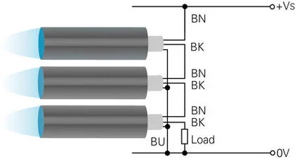
Serial Connection
3-wire DC (PNP circuit shown)
The voltage drop across each conductive sensor reduces the voltage available to drive the load. Therefore, the number of proximity switches that can be connected in series is limited and can be determined by calculating the load requirement by the sum of the individual voltage drops.
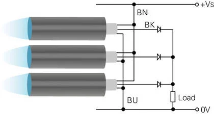
Parallel Connection
3-wire DC
3-wire DC sensors can be connected in parallel as shown. However, a parallel connection must include a decoupling diode.
Connection Diagrams
The diagrams mentioned show the undamped output. When an object is within the sensor's scanning range, the sensor is damped. In the diagrams, Z represents the typical load resistor location; Uz indicates the voltage applied to this load resistor. If Uz = high (≈ +Vs), current flows; If Uz = low (≈ 0 V), no current flows through the load resistor. The load resistance between the output and +Vs is called pull-up resistance, and the load resistance between the output and 0 V is called pull-down resistance.
PNP or NPN Output
Sensors with PNP or NPN outputs have a 3-wire design (+Vs, output and 0 V) and operate with direct current (DC). The load resistance of PNP sensors is between the output and 0 V (pull-up resistance), while the load resistance of NPN sensors is between +Vs and the output (pull-up resistance). As a result, the PNP output is connected to the positive voltage source during switching (positive switching output), while the NPN output is connected to the negative voltage source during switching (negative switching output).
Normally open contacts and/or normally closed contacts define the switching function. Normally open contacts are called normally open (NO), normally closed contacts are called normally closed (NC). During damping with an object, sensors with normally open function establish contact (Uz = high), while sensors with normally closed function disconnect (Uz = low).
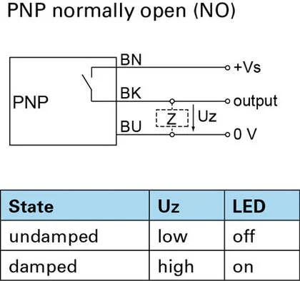
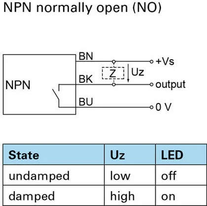
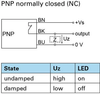
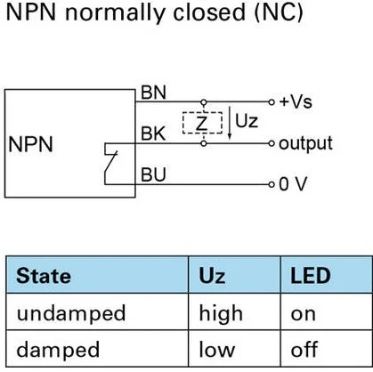
Explanatory Notes and Connection Diagrams
The diagrams mentioned show the undamped output. When an object is within the sensor's scanning range, the sensor is damped. In the diagrams, Z represents the typical load resistor location; Uz indicates the voltage applied to this load resistor. If Uz = high (≈ +Vs), current flows; If Uz = low (≈ 0 V), no current flows through the load resistor. The load resistance between the output and +Vs is called pull-up resistance, and the load resistance between the output and 0 V is called pull-down resistance.
Assembly and Assembly Procedure
To prevent unintentional interference with the measurement field and to achieve maximum detection distances, the installation instructions must be followed and the specified minimum distances must be maintained. If minimum distances are exceeded, a reduction in detection distances can be expected. A direct sensor test is recommended in practice.
The correction factors for different installation situations specified in the sensor data sheet take precedence over the general guidelines below.
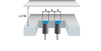
Protected (recessed) mounting
The sensor can be flush mounted in a metal plate. The choice of carrier material may have an impact on the detection distance.
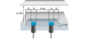
Unshielded (non-recessed) installation
There should be a gap equal to the diameter of the detection head and there should be no metal interference in this area. When this rule is followed, the electric field strength is weakened less, resulting in a greater detection distance.
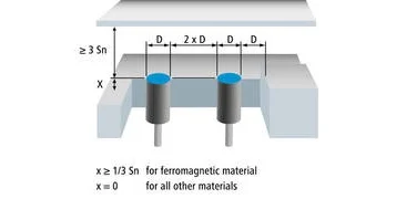
Semi-protected installation
When mounted in ferromagnetic material, these sensors need a metal-free gap (x) behind the active area. Sensors can be installed shielded (recessed) when mounted on non-ferrous materials such as colored metals. Always read and follow the installation instructions for distance measuring sensors.
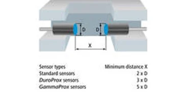
Mutual Assembly
Minimum distances must be observed to prevent mutually positioned sensors from affecting each other.
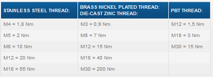
Maximum Mounting Torque
To avoid damaging the proximity switches during installation, the default torque value should not be exceeded. Reduce torque values by 30% on the surface of the sensor.
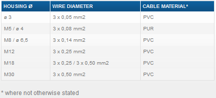
Assembly Instructions for Non-Threaded Bodies
Strong and occasional body loads, such as those occurring during fastening with grub screws, should be avoided (IFRM 03, 04, 06). Improper installation can cause irreversible damage to the proximity switch. Sensors with a housing diameter of 6.5 mm can be best mounted with the plastic support bracket 10109474.
Installation/Teach-In
Baumer Teach-In Functions
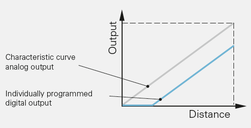
Baumer AlphaProx sensors, linear characteristic curve, factor 1 sensors and high-precision sensors have a teach function with several teach modes. This allows the measuring range to be freely configured within specified limits. For example, if a small measuring range with large signal amplitude is required, this can be limited to a few millimeters. Additionally, the operating direction of the analog output can be reversed when necessary.
In addition, the opening and closing points of a digital output can also be defined. These points may be within or outside the individually programmed measuring range.
1-Point Teach Analog
Teaching the starting position (e.g. 0 V), center position (e.g. 5 V) or end position (e.g. 10 V) of the measuring range. In this teach mode, the output characteristic curve can be shifted without changing the sensitivity or slope of the characteristic curve. This is used to electronically compensate installation tolerances, thus enabling quick and easy adjustments in series production.

2-Point Teach Analog
2-point teach is used in applications where two reference points (start and end position) can be set. By adjusting the measuring range, the sensitivity or slope of the output characteristic curve can be perfectly adapted to the application and installation and mechanical production tolerances can be compensated. The first taught position always corresponds to the starting value (e.g. 0 V) and the second position to the end value (e.g. 10 V). Depending on the teaching order, the output characteristic curve increases or decreases as the target object approaches.
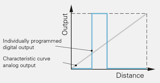
Window Teach Digital
Analogue distance sensors with an additional digital output offer a teach window digital instead of the 2-point Teach analogue. This allows defining the valid or invalid distance range between the target and the sensor for the digital output - independently of the analog output signal. Depending on the teaching sequence, the digital output will be HIGH or LOW if the measured object is within the taught distance range. This teach function is used to define a separate switching signal independent of the analog signal, for example for an end position circuit.
Resetting to Factory Settings
All sensors with a teach function have a factory reset function to reset the sensor to factory settings.