Installation of Hall Sensors
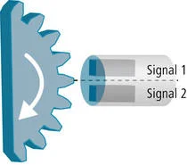
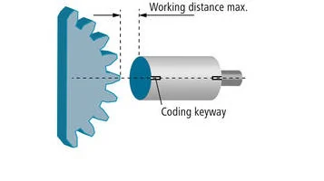
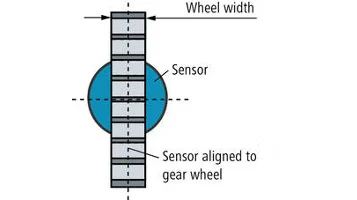
When mounting the Hall sensor, make sure that the measured object (gear wheel) is within the maximum operating distance. Additionally, the sensor must be axially aligned to the gear wheel. Observe the minimum gear width to ensure sufficient signal reserves. The working distance and installation instructions apply to gear wheels with involute tooth profile (DIN 867).
Rotation Direction of Multi-Channel Sensors
Two Hall semiconductor elements provide two different signal outputs for each tooth, shifted by 90°, and thus can detect both the rotation speed and direction of a gear wheel. In a gear wheel rotating clockwise, Channel A will be ahead of Channel B.

Setting
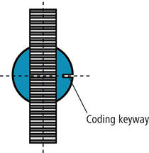
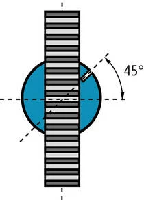
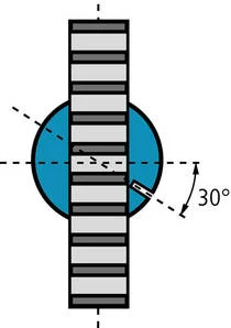
To ensure correct operation of the two-channel output, the Hall elements of multi-channel Hall sensors must be aligned with respect to the tooth module of the gear wheel. The sensor must be aligned to the teeth of the gear wheel using the coding thread and taking into account the gear module.