Mounting Magnetic and Cylinder Sensors
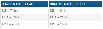
Maximum Mounting Torque
To prevent damage to the sensor during installation, comply with the specified maximum installation torque.
External Threaded Cylindrical Design
The values applied to the sensing head should be reduced by approximately 30%.
Rectangular Design, Female (Internal) Thread
- M2:0.1Nm
- M2.5:0.1Nm
- M3:0.3Nm
Mounting Magnetic Sensors
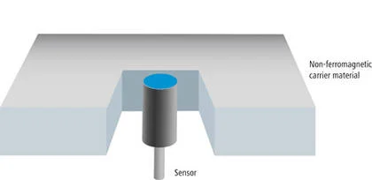
Unshielded (Recessed) Mounting
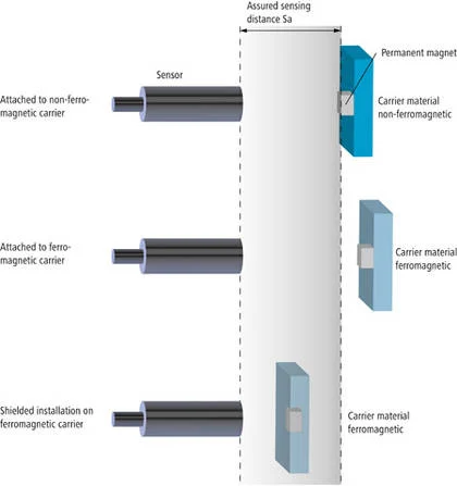
Magnetoresistive proximity switches are designed for unshielded (recessed) mounting, meaning that the sensing surface sits flat against the carrier surface. The carrier material should not be ferromagnetic. Unshielded mounting in ferromagnetic material reduces the detection range by up to 25%. Unshielded or non-recessed mounting (where the sensing surface protrudes diameter from the ferromagnetic carrier surface) increases the sensing distance by up to 25%.
Permanent Magnet - Alloy
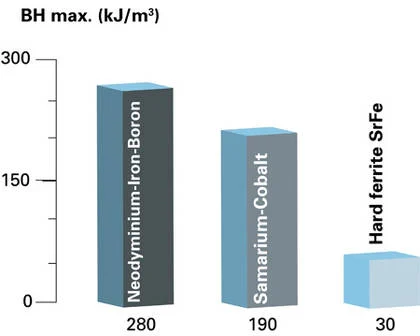
The switching distance of the magnetic sensor depends on the magnet used. Not only the size, but also the alloy of the permanent magnet plays a decisive role. The higher the energy product of the magnetic alloy in kJ/m³, the stronger the magnetic field and therefore the longer the switching distance.
Permanent Magnet - Alignment
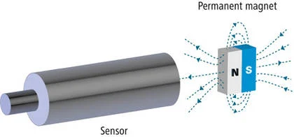
Essentially, magnetoresistive proximity switches are pole neutral, meaning the sensor detects both the north and south pole of the permanent magnet. To ensure reliable detection, it is recommended to always mount one pole of the permanent magnet aligned with the sensor.
Permanent Magnet - Assembly
The mounting method of the permanent magnet plays an important role in the detection distance. When mounted on a non-mooring carrier, there is almost no noticeable effect on detection range. However, a permanent magnet mounted unprotected on a mooring carrier can increase switch distance by 25%. If the permanent magnet is mounted flat or shielded on a mooring carrier, the detection distance can be reduced by 40% (always depending on the reliable detection distance). If the permanent magnet is to be mounted with screws, it is always recommended to use non-ferrous screws (e.g. stainless steel).
Installation of Magnetic Cylinder Sensors
Setting
The magnetic fields of permanent magnets inside the cylinders are distributed and vary in their properties depending on the cylinder type. Therefore, it is not possible to specify the exact trigger point of the sensor. Follow these steps to ensure the roller sensor is placed in the correct position:
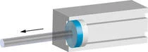
- Move Piston to Required Switch Position
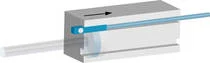
2. Move the roller sensor in its housing in the opposite direction of step one. On round cylinders or Tie-Rod cylinders: First mount the sensor loosely to the cylinder with a clamp or bolt.
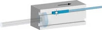
3. After the LED is on, pull the sensor back a little and ensure reliable switch operation.
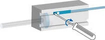
4. Fix the sensor.
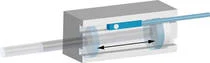
5. Verify the switch point using the LED.
Slotted Cylinder Assembly
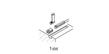
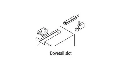
Conventional cylinders usually offer standard T or C slots. Cylinder sensors are simply inserted into the housing and secured – either using a grub screw or with a metal plate, which is locked into the housing after the clamping screw is tightened.

Assembly of Round Cylinders or Tension Rod Cylinders
Some commonly used round cylinders or tension rod cylinders may not provide a housing for sensor mounting. In this case, C- or T-mount sensors are mounted using clamps or bolts.
Installation of Special Slots
C-slot sensors can also be mounted in T-slots using the adapter from the accessory kit. Additionally, adapters for special mounts (e.g. sprocket mounts) are also available.